
User Manual
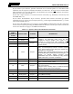
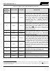
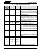
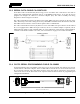
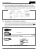
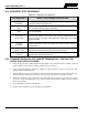
Table Of Contents
- 1 REGULATORY AND SAFETY INFORMATION
- 1.1 SAFETY SYMBOL CONVENTIONS
- 1.2 RF ENERGY EXPOSURE AWARENESS AND CONTROL INFORMATION FOR FCC OCCUPATIONAL USE REQUIREMENTS
- 1.3 COMPLIANCE WITH RF EXPOSURE STANDARDS
- 1.4 REGULATORY APPROVALS
- OCCUPATIONAL SAFETY GUIDELINES AND SAFETY TRAINING INFORMATION
- 1.6 COMMON HAZARDS
- 1.7 SAFE DRIVING RECOMMENDATIONS
- 1.8 OPERATING RULES AND REGULATIONS
- 1.9 OPERATING TIPS
- 2 SPECIFICATIONS
- 3 INTRODUCTION
- 4 UNPACKING AND CHECKING THE EQUIPMENT
- 5 PLANNING THE INSTALLATION
- 6 ANTENNA INSTALLATION
- 6.1 ANTENNA MOUNTING LOCATIONS
- 6.2 ANTENNA INSTALLATION PROCEDURES
- 7 FRONT-MOUNT RADIO INSTALLATION
- 8 REMOTE-MOUNT RADIO INSTALLATION
- 8.1 MOUNTING THE REMOTE-MOUNT RADIO
- 8.2 REMOTE-MOUNT RADIO’S DC POWER INSTALLATION
- 8.3 CONTROL HEAD INSTALLATION
- 8.3.1 General Information on the CH100 Control Head
- 8.3.2 General Information on the CH721 Control Head
- 8.3.3 Multi-Head Radio Installations
- 8.3.4 Control Head Mechanical Installation
- 8.3.5 Control Head-to-Radio CAN Cable Connections
- 8.3.6 Control Head Power Cable Installation
- 8.3.7 Using Vehicle Fuse and TTap Kit (Optional) Instead of Waterproof Inline Fuse Holder (Standard)
- 9 SPEAKER INSTALLATION
- 10 MICROPHONE ATTACHMENT
- 11 OPTIONAL CABLES AND CONNECTIONS
- 12 GPS NMEA-FORMATTED DATA CONNECTION
- 13 INITIAL POWER-UP TEST
- 14 PERFORMANCE TESTS
- 15 COMPLETE THE INSTALLATION
- 16 WARRANTY REGISTRATION
- 17 WARRANTY

14221-1200-4000, Rev. A
79
14 PERFORMANCE TESTS
This section includes procedures to verify the performance of the installation’s mobile antenna system.
There are two (2) test procedures in this section:
• Transmitting into a 50-Ohm RF Terminator (“Dummy Load”) — Section 14.2 — This test
verifies the radio’s RF output power is satisfactory.
• Transmitting into the Mobile Antenna — Section 14.3 — This test verifies the radio’s multiband
antenna system is satisfactory.
The multiband antenna element is an untuned antenna with a Voltage Standing-Wave
Ratio (VSWR) of ≤3:1. If an antenna analyzer is available, the antenna installation
should be tested with it prior to performing tests presented in this section. Tests with an
antenna analyzer can be performed without powering-up the radio. Tests with an
antenna analyzer are beyond the scope of this manual, and therefore, an analyzer is not
listed in Table 14-1. Refer to the analyzer’s operating/user manual for complete
testing instructions.
The accuracy of test results depends upon a DC power source in the range of 13.6 volts
DC ±10%, with a current capacity of greater than 20 amps. Make sure the vehicle’s
battery is fully charged by running the engine for a few minutes before the test, and
keep the engine running during the test procedures. Abide by
the following
WARNING!
If the vehicle’s engine must remain running, the vehicle location should be well
ventilated so exhaust fumes from the engine do not cause harm!
If a vehicle equipped with this radio requires jump-starting, the radio installation’s
main AGC fuse (20-amp) should be removed from the holder prior to jump-starting.
Doing so will prevent damage to the radio system.
Prior to installation, the radio’s power level should be configured appropriately. The
wide range of power levels indicated in the following procedures takes into account
such things as: customer’s requirements; measurement errors, especially to include
uncalibrated equipment; cabling losses; and voltage and temperature variations. By no
means should the result from Performance Testing in this section be construed as the
exact value of power level output from the radio, as the value is set and more
accurately measured in the factory. The values obtained in these test procedures
determine a successful installation only.
NOTE
CAUTION
WARNING
CAUTION
NOTE