
User Manual
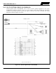
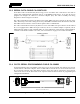
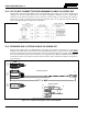
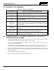
Table Of Contents
- 1 REGULATORY AND SAFETY INFORMATION
- 1.1 SAFETY SYMBOL CONVENTIONS
- 1.2 RF ENERGY EXPOSURE AWARENESS AND CONTROL INFORMATION FOR FCC OCCUPATIONAL USE REQUIREMENTS
- 1.3 COMPLIANCE WITH RF EXPOSURE STANDARDS
- 1.4 REGULATORY APPROVALS
- OCCUPATIONAL SAFETY GUIDELINES AND SAFETY TRAINING INFORMATION
- 1.6 COMMON HAZARDS
- 1.7 SAFE DRIVING RECOMMENDATIONS
- 1.8 OPERATING RULES AND REGULATIONS
- 1.9 OPERATING TIPS
- 2 SPECIFICATIONS
- 3 INTRODUCTION
- 4 UNPACKING AND CHECKING THE EQUIPMENT
- 5 PLANNING THE INSTALLATION
- 6 ANTENNA INSTALLATION
- 6.1 ANTENNA MOUNTING LOCATIONS
- 6.2 ANTENNA INSTALLATION PROCEDURES
- 7 FRONT-MOUNT RADIO INSTALLATION
- 8 REMOTE-MOUNT RADIO INSTALLATION
- 8.1 MOUNTING THE REMOTE-MOUNT RADIO
- 8.2 REMOTE-MOUNT RADIO’S DC POWER INSTALLATION
- 8.3 CONTROL HEAD INSTALLATION
- 8.3.1 General Information on the CH100 Control Head
- 8.3.2 General Information on the CH721 Control Head
- 8.3.3 Multi-Head Radio Installations
- 8.3.4 Control Head Mechanical Installation
- 8.3.5 Control Head-to-Radio CAN Cable Connections
- 8.3.6 Control Head Power Cable Installation
- 8.3.7 Using Vehicle Fuse and TTap Kit (Optional) Instead of Waterproof Inline Fuse Holder (Standard)
- 9 SPEAKER INSTALLATION
- 10 MICROPHONE ATTACHMENT
- 11 OPTIONAL CABLES AND CONNECTIONS
- 12 GPS NMEA-FORMATTED DATA CONNECTION
- 13 INITIAL POWER-UP TEST
- 14 PERFORMANCE TESTS
- 15 COMPLETE THE INSTALLATION
- 16 WARRANTY REGISTRATION
- 17 WARRANTY

14221-1200-4000, Rev. A
78
13 INITIAL POWER-UP TEST
1. Carefully reconnect the vehicle’s battery ground cable.
2. At the radio’s main waterproof (HFB-type) fuse holder installed near the vehicle battery, insert the
20-amp AGC-type fuse that was included with the radio’s DC Power Cable. The 15-amp fuse
included with the cable is not used in this application of the cable.
3. Tie and stow all fuse holders at this location to prevent excess vibration/movement.
4. If not already, temporarily connect the mobile antenna cable from the vehicle-mounted mobile
antenna to the female TNC RF connector on the rear panel of the radio. This is a temporary
connection until performance tests in Section 14 are complete.
5. Permanently connect the antenna cable from the GPS antenna (or mobile/GPS combo antenna) to the
female SMA connector on the rear panel of the radio. The male SMA connector on most GPS antenna
cables has a 5/16-inch hex collar, so the use of a wrench of this same size is normally required for
tightening. However, some may have collars with only knurled surfaces, so a standard wrench or
torque wrench cannot be used. In either case, do not
over tighten the connector and do not twist the
cable when tightening.
6. If the installation is wired so the vehicle’s ignition key/switch turns the radio on and off, turn the
switch to the Accessory or Run position.
7. If the control head is not already powered up, do so by rotating its on/off/volume control clockwise
out of the detent position.
8. Verify the control head has powered-up by observing its display. If the display is not functioning,
refer to Section 8.2.1 as necessary.
As long as the software configuration parameters have been loaded, successful installation is almost
immediately realized:
• After a short boot-up sequence, the control head displays system/zone and/or the selected talk
group.
• If no errors are displayed, the installation is most-likely properly wired.
• If an error is displayed, recheck all cable connections, verify all fuses are properly installed, and
verify battery power on the load side of the fuses, etc. If problems persist, contact the Technical
Assistance Center (see page 21).
• Consult the Operator’s Manual for operational information.
9. Advance to Section 14 and complete the performance test procedures.