
User Manual
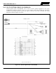
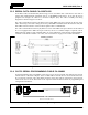
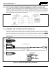
Table Of Contents
- 1 REGULATORY AND SAFETY INFORMATION
- 1.1 SAFETY SYMBOL CONVENTIONS
- 1.2 RF ENERGY EXPOSURE AWARENESS AND CONTROL INFORMATION FOR FCC OCCUPATIONAL USE REQUIREMENTS
- 1.3 COMPLIANCE WITH RF EXPOSURE STANDARDS
- 1.4 REGULATORY APPROVALS
- OCCUPATIONAL SAFETY GUIDELINES AND SAFETY TRAINING INFORMATION
- 1.6 COMMON HAZARDS
- 1.7 SAFE DRIVING RECOMMENDATIONS
- 1.8 OPERATING RULES AND REGULATIONS
- 1.9 OPERATING TIPS
- 2 SPECIFICATIONS
- 3 INTRODUCTION
- 4 UNPACKING AND CHECKING THE EQUIPMENT
- 5 PLANNING THE INSTALLATION
- 6 ANTENNA INSTALLATION
- 6.1 ANTENNA MOUNTING LOCATIONS
- 6.2 ANTENNA INSTALLATION PROCEDURES
- 7 FRONT-MOUNT RADIO INSTALLATION
- 8 REMOTE-MOUNT RADIO INSTALLATION
- 8.1 MOUNTING THE REMOTE-MOUNT RADIO
- 8.2 REMOTE-MOUNT RADIO’S DC POWER INSTALLATION
- 8.3 CONTROL HEAD INSTALLATION
- 8.3.1 General Information on the CH100 Control Head
- 8.3.2 General Information on the CH721 Control Head
- 8.3.3 Multi-Head Radio Installations
- 8.3.4 Control Head Mechanical Installation
- 8.3.5 Control Head-to-Radio CAN Cable Connections
- 8.3.6 Control Head Power Cable Installation
- 8.3.7 Using Vehicle Fuse and TTap Kit (Optional) Instead of Waterproof Inline Fuse Holder (Standard)
- 9 SPEAKER INSTALLATION
- 10 MICROPHONE ATTACHMENT
- 11 OPTIONAL CABLES AND CONNECTIONS
- 12 GPS NMEA-FORMATTED DATA CONNECTION
- 13 INITIAL POWER-UP TEST
- 14 PERFORMANCE TESTS
- 15 COMPLETE THE INSTALLATION
- 16 WARRANTY REGISTRATION
- 17 WARRANTY

14221-1200-4000, Rev. A
77
12 GPS NMEA-FORMATTED DATA CONNECTION
To obtain GPS NMEA-formatted serial data from the radio, Option Cable CA-012349-001 is required.
Follow this procedure to complete the GPS NMEA-formatted serial data connections:
1. Obtain Option Cable CA-012349-001. Each “leg” of this cable is approximately 65 inches long (166
centimeters).
2. Connect the cable’s 44-pin D-subminiature (DB-44) male connector to the DB-44 female connector
on the rear panel of the radio. Tighten the two jackscrews with a small flathead screwdriver. Do not
over-tighten.
3. Connect the cable’s DB-9 female connector to the computer’s serial port DB-9 male connector—
either directly or extended via cable CA-013671-020 (a 20-foot-long cable); see Section 11.3.
Tighten the screws firmly, and then route the cabling as required. If the computer is not equipped with
a DB-9 serial port connector, the use of a suitable adapter is required, such as USB-to-RS-232
Adapter Cable CN24741-0001.
4. Follow the manufacturer’s instructions on processing the NMEA-formatted GPS data from the radio.
If the Option Cable is not available, a 3-wire serial cable can be field-fabricated. On the
radio end, this cable must interface to the three GPS-related signals of the radio’s 44-pin
I/O Cable connector (pins 7, 31 and 32). See Table 11-1 for additional information.
Industry software to process GPS information through this interface is not supported by Harris.
NOTE