
User Manual
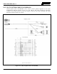
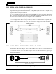
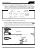
Table Of Contents
- 1 REGULATORY AND SAFETY INFORMATION
- 1.1 SAFETY SYMBOL CONVENTIONS
- 1.2 RF ENERGY EXPOSURE AWARENESS AND CONTROL INFORMATION FOR FCC OCCUPATIONAL USE REQUIREMENTS
- 1.3 COMPLIANCE WITH RF EXPOSURE STANDARDS
- 1.4 REGULATORY APPROVALS
- OCCUPATIONAL SAFETY GUIDELINES AND SAFETY TRAINING INFORMATION
- 1.6 COMMON HAZARDS
- 1.7 SAFE DRIVING RECOMMENDATIONS
- 1.8 OPERATING RULES AND REGULATIONS
- 1.9 OPERATING TIPS
- 2 SPECIFICATIONS
- 3 INTRODUCTION
- 4 UNPACKING AND CHECKING THE EQUIPMENT
- 5 PLANNING THE INSTALLATION
- 6 ANTENNA INSTALLATION
- 6.1 ANTENNA MOUNTING LOCATIONS
- 6.2 ANTENNA INSTALLATION PROCEDURES
- 7 FRONT-MOUNT RADIO INSTALLATION
- 8 REMOTE-MOUNT RADIO INSTALLATION
- 8.1 MOUNTING THE REMOTE-MOUNT RADIO
- 8.2 REMOTE-MOUNT RADIO’S DC POWER INSTALLATION
- 8.3 CONTROL HEAD INSTALLATION
- 8.3.1 General Information on the CH100 Control Head
- 8.3.2 General Information on the CH721 Control Head
- 8.3.3 Multi-Head Radio Installations
- 8.3.4 Control Head Mechanical Installation
- 8.3.5 Control Head-to-Radio CAN Cable Connections
- 8.3.6 Control Head Power Cable Installation
- 8.3.7 Using Vehicle Fuse and TTap Kit (Optional) Instead of Waterproof Inline Fuse Holder (Standard)
- 9 SPEAKER INSTALLATION
- 10 MICROPHONE ATTACHMENT
- 11 OPTIONAL CABLES AND CONNECTIONS
- 12 GPS NMEA-FORMATTED DATA CONNECTION
- 13 INITIAL POWER-UP TEST
- 14 PERFORMANCE TESTS
- 15 COMPLETE THE INSTALLATION
- 16 WARRANTY REGISTRATION
- 17 WARRANTY

14221-1200-4000, Rev. A
75
11.3 SERIAL DATA CABLE CA-013671-020
Serial Data Cable CA-013671-020 (20 feet long) can be used make data connections to the radio to
support data communications equipment such as a GPS NMEA-format device. It can also be used to
program and configure the radio via a Personal Computer (PC). The cable’s assembly and wiring
diagrams are shown in Figure 11-3 below.
The cable’s male DB-9 connector (J1) mates to the female DB-9 serial port connector on the rear of the
radio. Alternately, if the cable is being used to carry GPS NMEA-formatted serial data from the radio, this
male DB-9 connector mates to connector P5 of Option Cable CA-012349-001.
The cable’s female DB-9 connector (J2) mates to a PC’s male DB-9 serial port connector. If the utilized
PC is not equipped with a DB-9 serial port connector, the use of a suitable adapter is required, such as
USB-to-RS-232 Adapter Cable CN24741-0001. As of the publication of this manual, CN24741-0001 is
available via the Harris Customer Care center; refer to Section 3.3 on page 21 for contact information.
(Made From PS-CA-013671 Rev. -)
Figure 11-3: Serial Data Cable CA-013671-020
11.4 CH-721 SERIAL PROGRAMMING CABLE CA-104861
Serial Programming Cable CA-104861 (5 feet long) can be used to program and configure the CH-721
control head via a Personal Computer. It has a female DB-9 connector on one end for connection to the
PC’s serial port connector and a male DB-9 connector on the other end for connection to the serial port
connector on the rear of the head. Refer to the respective Software Release Notes for programming and
configuration information.
(Made From PS-CA-104861 Rev. B)
Figure 11-4: CH-721 Serial Programming Cable CA-104861
5 FEET
(1.524 METERS)
ASSEMBLY DIAGRAM