
User Manual
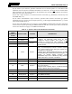
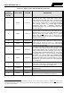
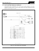
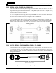
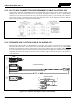
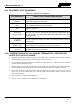
Table Of Contents
- 1 REGULATORY AND SAFETY INFORMATION
- 1.1 SAFETY SYMBOL CONVENTIONS
- 1.2 RF ENERGY EXPOSURE AWARENESS AND CONTROL INFORMATION FOR FCC OCCUPATIONAL USE REQUIREMENTS
- 1.3 COMPLIANCE WITH RF EXPOSURE STANDARDS
- 1.4 REGULATORY APPROVALS
- OCCUPATIONAL SAFETY GUIDELINES AND SAFETY TRAINING INFORMATION
- 1.6 COMMON HAZARDS
- 1.7 SAFE DRIVING RECOMMENDATIONS
- 1.8 OPERATING RULES AND REGULATIONS
- 1.9 OPERATING TIPS
- 2 SPECIFICATIONS
- 3 INTRODUCTION
- 4 UNPACKING AND CHECKING THE EQUIPMENT
- 5 PLANNING THE INSTALLATION
- 6 ANTENNA INSTALLATION
- 6.1 ANTENNA MOUNTING LOCATIONS
- 6.2 ANTENNA INSTALLATION PROCEDURES
- 7 FRONT-MOUNT RADIO INSTALLATION
- 8 REMOTE-MOUNT RADIO INSTALLATION
- 8.1 MOUNTING THE REMOTE-MOUNT RADIO
- 8.2 REMOTE-MOUNT RADIO’S DC POWER INSTALLATION
- 8.3 CONTROL HEAD INSTALLATION
- 8.3.1 General Information on the CH100 Control Head
- 8.3.2 General Information on the CH721 Control Head
- 8.3.3 Multi-Head Radio Installations
- 8.3.4 Control Head Mechanical Installation
- 8.3.5 Control Head-to-Radio CAN Cable Connections
- 8.3.6 Control Head Power Cable Installation
- 8.3.7 Using Vehicle Fuse and TTap Kit (Optional) Instead of Waterproof Inline Fuse Holder (Standard)
- 9 SPEAKER INSTALLATION
- 10 MICROPHONE ATTACHMENT
- 11 OPTIONAL CABLES AND CONNECTIONS
- 12 GPS NMEA-FORMATTED DATA CONNECTION
- 13 INITIAL POWER-UP TEST
- 14 PERFORMANCE TESTS
- 15 COMPLETE THE INSTALLATION
- 16 WARRANTY REGISTRATION
- 17 WARRANTY

14221-1200-4000, Rev. A
71
P2, the cable’s 2-pin connector, provides connections for an external speaker in a front-mount radio
installation. For the respective installation information, see Section 9.1. P2 is not
used in a remote-mount
radio installation, since the audio amplifier in the head drives the external speaker (speaker connection is
made at the rear of the control head).
P3, the cable’s 6-pin connector, is a connector for basic accessories (e.g., hookswitch, external relay with
back-EMF diode, etc.).
P4, the cable’s D-subminiature 25-pin connector, provides audio and data connections for optional
equipment such as an external siren and light system (e.g., Federal Signal SS2000 SmartSiren
®
), external
relay with back-EMF diode, etc.
P5, the cable’s D-subminiature 9-pin connector, provides NMEA-formatted GPS serial data connections
for the external computer processing the NMEA-formatted GPS data received by the radio’s internal GPS
receiver. See Section 12 on page 77 for additional information.
Table 11-1: Option Cable CA-012349-001 Interconnections
44-PIN I/O
CABLE
CONNECTOR
P1 PIN
SIGNAL NAME TO/FROM DESCRIPTION
19 SPKR1
P2 pin 1
Speaker Audio Outputs 1 and 2. In a front-
mount radio
installation, this differential output drives
the radio
installation’s external speaker. This output is not
functional in a remote-mount radio installation;
in this
case,
the speaker output from the control head drives the
external speaker.
20 SPKR1
21 SPKR2
P2 pin 2
22 SPKR2
10 OUT2 P3 pin 1
Digital Output 2 (open-collector, 100 mA / 17 V maxi-
mum). An external pull-up resistor is
needed if required
by the external device’s input during the high/off state.
Use P3 pin 2 or 4 for ground.
Configure via the “External Output Control Line 2” in
Radio
Personality Manager’s (RPM’s) External I/O dialog box.
For
example, an external logging recorder’s record
enable/disable input can be controlled by setting “
External
Output Control Line 2” to “Extern. Tx Indicator.”
7 GND P3 pins 2 & 4
Chassis Ground (fused on radio’s PK Board).
26 HKSW P3 pin 3
Digital Input for Hookswitch (default) or for radio
PTT.
Active = Ground. Inactive = Open.
25 INP2 P3 pin 5
Digital Input 2. Active = Ground. Inactive =
Open. Use P3
pin 2 or 4 for ground.
Configure
via the “Auxiliary Input 2” in Radio Personality
Manager’s (RPM’s) External I/O dialog Box.
28 SWA+ P3 pin 6
Switched A+ (DC Power) Output.
8 GND P4 pin 1
Chassis ground (fused on PK Board).
30 DGPS_DATA P4 pin 4
GPS Receiver Module DGPS Correction Data
Serial Data
Input (NMEA formatted).
4 EXTRX P4 pin 5
External Rx Audio Input (from external/2
nd
receiver; summed).
9 RESERVED P4 pin 7
Not used.