
User Manual
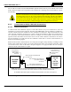

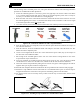

Table Of Contents
- 1 REGULATORY AND SAFETY INFORMATION
- 1.1 SAFETY SYMBOL CONVENTIONS
- 1.2 RF ENERGY EXPOSURE AWARENESS AND CONTROL INFORMATION FOR FCC OCCUPATIONAL USE REQUIREMENTS
- 1.3 COMPLIANCE WITH RF EXPOSURE STANDARDS
- 1.4 REGULATORY APPROVALS
- OCCUPATIONAL SAFETY GUIDELINES AND SAFETY TRAINING INFORMATION
- 1.6 COMMON HAZARDS
- 1.7 SAFE DRIVING RECOMMENDATIONS
- 1.8 OPERATING RULES AND REGULATIONS
- 1.9 OPERATING TIPS
- 2 SPECIFICATIONS
- 3 INTRODUCTION
- 4 UNPACKING AND CHECKING THE EQUIPMENT
- 5 PLANNING THE INSTALLATION
- 6 ANTENNA INSTALLATION
- 6.1 ANTENNA MOUNTING LOCATIONS
- 6.2 ANTENNA INSTALLATION PROCEDURES
- 7 FRONT-MOUNT RADIO INSTALLATION
- 8 REMOTE-MOUNT RADIO INSTALLATION
- 8.1 MOUNTING THE REMOTE-MOUNT RADIO
- 8.2 REMOTE-MOUNT RADIO’S DC POWER INSTALLATION
- 8.3 CONTROL HEAD INSTALLATION
- 8.3.1 General Information on the CH100 Control Head
- 8.3.2 General Information on the CH721 Control Head
- 8.3.3 Multi-Head Radio Installations
- 8.3.4 Control Head Mechanical Installation
- 8.3.5 Control Head-to-Radio CAN Cable Connections
- 8.3.6 Control Head Power Cable Installation
- 8.3.7 Using Vehicle Fuse and TTap Kit (Optional) Instead of Waterproof Inline Fuse Holder (Standard)
- 9 SPEAKER INSTALLATION
- 10 MICROPHONE ATTACHMENT
- 11 OPTIONAL CABLES AND CONNECTIONS
- 12 GPS NMEA-FORMATTED DATA CONNECTION
- 13 INITIAL POWER-UP TEST
- 14 PERFORMANCE TESTS
- 15 COMPLETE THE INSTALLATION
- 16 WARRANTY REGISTRATION
- 17 WARRANTY

14221-1200-4000, Rev. A
70
11 OPTIONAL CABLES AND CONNECTIONS
11.1 OPTION CABLE CA-012349-001
Option Cable CA-012349-001 connects to the 44-pin I/O connector on the rear of the radio. It breaks out
into several smaller standardized connectors, allowing straightforward access to external I/O interfaces
provided by the radio. The cable also shortens radio removal and re-installation time when required. The
cable is shown in Figure 11-1 below. The cable’s 44-pin D-subminiature connector that mates with the
connector on the rear of the radio is identified P1.
Observe caution before connecting any external device to the radio via its 44-pin I/O
connector. If an external device has its own DC power source/cable (i.e., if it is
powered separately from the radio), both the radio and the external device must be
properly grounded to the vehicle before connecting the two units together and before
making a positive (+) DC power connection to either unit. Otherwise, equipment
damage may occur.
(Made From PS-CA-012349 Sh. 1 and 2, Rev. G)
Figure 11-1: Option Cable CA-012349-001
CAUTION
Approximately 66 inches
(170 centimeters)
P1
(Pin-Out
View)
P1
(Side
View)
P6
ASSEMBLY DIAGRAM
WIRING DIAGRAM
P2
P3
P5
P4