
User Manual
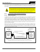

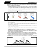

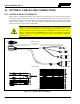
Table Of Contents
- 1 REGULATORY AND SAFETY INFORMATION
- 1.1 SAFETY SYMBOL CONVENTIONS
- 1.2 RF ENERGY EXPOSURE AWARENESS AND CONTROL INFORMATION FOR FCC OCCUPATIONAL USE REQUIREMENTS
- 1.3 COMPLIANCE WITH RF EXPOSURE STANDARDS
- 1.4 REGULATORY APPROVALS
- OCCUPATIONAL SAFETY GUIDELINES AND SAFETY TRAINING INFORMATION
- 1.6 COMMON HAZARDS
- 1.7 SAFE DRIVING RECOMMENDATIONS
- 1.8 OPERATING RULES AND REGULATIONS
- 1.9 OPERATING TIPS
- 2 SPECIFICATIONS
- 3 INTRODUCTION
- 4 UNPACKING AND CHECKING THE EQUIPMENT
- 5 PLANNING THE INSTALLATION
- 6 ANTENNA INSTALLATION
- 6.1 ANTENNA MOUNTING LOCATIONS
- 6.2 ANTENNA INSTALLATION PROCEDURES
- 7 FRONT-MOUNT RADIO INSTALLATION
- 8 REMOTE-MOUNT RADIO INSTALLATION
- 8.1 MOUNTING THE REMOTE-MOUNT RADIO
- 8.2 REMOTE-MOUNT RADIO’S DC POWER INSTALLATION
- 8.3 CONTROL HEAD INSTALLATION
- 8.3.1 General Information on the CH100 Control Head
- 8.3.2 General Information on the CH721 Control Head
- 8.3.3 Multi-Head Radio Installations
- 8.3.4 Control Head Mechanical Installation
- 8.3.5 Control Head-to-Radio CAN Cable Connections
- 8.3.6 Control Head Power Cable Installation
- 8.3.7 Using Vehicle Fuse and TTap Kit (Optional) Instead of Waterproof Inline Fuse Holder (Standard)
- 9 SPEAKER INSTALLATION
- 10 MICROPHONE ATTACHMENT
- 11 OPTIONAL CABLES AND CONNECTIONS
- 12 GPS NMEA-FORMATTED DATA CONNECTION
- 13 INITIAL POWER-UP TEST
- 14 PERFORMANCE TESTS
- 15 COMPLETE THE INSTALLATION
- 16 WARRANTY REGISTRATION
- 17 WARRANTY

14221-1200-4000, Rev. A
68
9 SPEAKER INSTALLATION
9.1 FRONT-MOUNT RADIO INSTALLATION
In a front-mount radio installation, total speaker cable length (of both cables) is approximately 10 feet
(308 centimeters). Therefore, to include service loops in these cables, the speaker must be mounted within
approximately 9.5 feet (290 centimeters) of the radio.
1. Select a location for the speaker that will allow for proper listening range at moderate volume.
2. Install the speaker using the hardware and mounting bracket supplied with it. For the speaker’s part
number, see Table 4-3 on page 24.
3. Route the speaker cable to the rear of the radio.
4. Connect Option Cable CA-012349-001 (item 5 in Table 4-3) to the DB-44 connector on the rear of
the radio. Tighten the cable’s two (2) jackscrews securely. See Section 11.1 for additional information
on this cable.
If the approximate speaker cable length of 10 feet is not long enough, 20-foot Speaker-
Only Option Cable CA-012349-007 can be used in place of Option Cable CA-012349-
001. However, Speaker-Only Option Cable CA-012349-001 does not
support any
optional connections at the 44-pin (DB-44) connector on the rear of the radio. Use of
Speaker-Only Option Cable CA-012349-007 will provide approximately 25 feet of total
cable length for the speaker connection.
5. Mate the Option Cable’s 2-pin connector (identified P2 with green and white wires) to the 2-pin
connector on the end of the speaker cable. A mild click will be sensed to confirm proper mating.
6. Route the cables out of the way of casual contact. Tie and stow as necessary.
9.2 REMOTE-MOUNT RADIO INSTALLATION
In a remote-mount mobile radio installation, an audio amplifier in the head drives the external speaker.
For this case, total speaker cable length of both cables between the control head and speaker is
approximately five (5) feet. Therefore, to include service loops in these cables, the speaker must be
mounted within approximately 4.5 feet of the installation’s control head.
1. Select a location for the speaker that will allow for proper listening range at moderate volume.
2. Install the speaker using the hardware and mounting bracket supplied with it. For the speaker’s part
number, see Table 4-5 (page 27).
3. Route the speaker cable to the rear of the control head.
4. Mate the 6-inch speaker cable, part number MAMROS0034-NN006, to the 2-pin connector at the rear
of the control head by visually aligning the ¾-moon-shaped keys of the connectors, and then pushing
and turning the outer locking ring of the cable connector clockwise until it stops. A mild click will be
sensed to confirm proper mating.
5. Connect the speaker cable’s 2-pin plastic connector to the respective mating connector on the 6-inch
speaker cable.
6. Route the cables out of the way of casual contact. Tie and stow as necessary.
In a multi-head installation, an audio amplifier in each control head drives the head’s
speaker. Therefore, no special speakers or relays are needed.
NOTE
NOTE