
User Manual
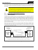

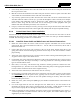
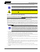
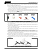

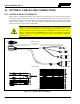
Table Of Contents
- 1 REGULATORY AND SAFETY INFORMATION
- 1.1 SAFETY SYMBOL CONVENTIONS
- 1.2 RF ENERGY EXPOSURE AWARENESS AND CONTROL INFORMATION FOR FCC OCCUPATIONAL USE REQUIREMENTS
- 1.3 COMPLIANCE WITH RF EXPOSURE STANDARDS
- 1.4 REGULATORY APPROVALS
- OCCUPATIONAL SAFETY GUIDELINES AND SAFETY TRAINING INFORMATION
- 1.6 COMMON HAZARDS
- 1.7 SAFE DRIVING RECOMMENDATIONS
- 1.8 OPERATING RULES AND REGULATIONS
- 1.9 OPERATING TIPS
- 2 SPECIFICATIONS
- 3 INTRODUCTION
- 4 UNPACKING AND CHECKING THE EQUIPMENT
- 5 PLANNING THE INSTALLATION
- 6 ANTENNA INSTALLATION
- 6.1 ANTENNA MOUNTING LOCATIONS
- 6.2 ANTENNA INSTALLATION PROCEDURES
- 7 FRONT-MOUNT RADIO INSTALLATION
- 8 REMOTE-MOUNT RADIO INSTALLATION
- 8.1 MOUNTING THE REMOTE-MOUNT RADIO
- 8.2 REMOTE-MOUNT RADIO’S DC POWER INSTALLATION
- 8.3 CONTROL HEAD INSTALLATION
- 8.3.1 General Information on the CH100 Control Head
- 8.3.2 General Information on the CH721 Control Head
- 8.3.3 Multi-Head Radio Installations
- 8.3.4 Control Head Mechanical Installation
- 8.3.5 Control Head-to-Radio CAN Cable Connections
- 8.3.6 Control Head Power Cable Installation
- 8.3.7 Using Vehicle Fuse and TTap Kit (Optional) Instead of Waterproof Inline Fuse Holder (Standard)
- 9 SPEAKER INSTALLATION
- 10 MICROPHONE ATTACHMENT
- 11 OPTIONAL CABLES AND CONNECTIONS
- 12 GPS NMEA-FORMATTED DATA CONNECTION
- 13 INITIAL POWER-UP TEST
- 14 PERFORMANCE TESTS
- 15 COMPLETE THE INSTALLATION
- 16 WARRANTY REGISTRATION
- 17 WARRANTY

14221-1200-4000, Rev. A
67
into an existing vehicle switched power wire, and a quick-disconnect terminal. The following installation
procedure is recommended for this optional kit:
1. Locate the switched ignition or “Accessory” power wire (typically at or near the vehicle’s fuse block
or in a vehicle wiring harness) that will be used for the switched ignition power source. It may be
necessary to consult the vehicle manufacturer’s wiring diagram.
2. Route the white wire of the control head’s DC Power Cable from the back of the head to an area near
the switched ignition power source. At the back of the head, be sure to maintain a cable service length
of at least six (6) inches and do not
loop the cable.
3. Cut a short section (6 to 8 inches) off the end of the white wire and strip each end of this short wire.
ATM 2-Amp Quick- T-Tap T-Tap
Fuse Holder ATM Disconnect Terminal for Terminal for
Fuse Terminal #22-18 AWG #16-14 AWG
(Gray) (Male Tab) Wire (Red) Wire (Blue)
(Shown Closed)
(Shown Open)
Figure 8-12: Contents of Vehicle Fuse and T-Tap Kit FS24473
4. From the Vehicle Fuse and T-Tap Kit, locate the male-tab quick-disconnect terminal and crimp it to
one end of the short wire.
5. From the same kit, locate the ATM fuse holder and crimp it to the other end of the short wire. The
holder has built-in crimpable joints.
6. Cut the excess length from the white wire of the control head’s power cable, strip it, and crimp it to
the other side of the ATM fuse holder.
7. Pull enough of the switched ignition source wire out of the vehicle’s wiring harness so one of the
T-tap terminals may be attached to it.
8. Two T-tap terminals are included in the kit. Based on the gauge of wire, select the proper terminal
size: Red is for use with a 22 to 18-AWG wire, and blue is for use with an 18 to 14-AWG wire.
9. Attach the selected T-tap terminal by fitting the wire into its wire groove and snapping the two halves
together with a pair of pliers as shown in Figure 8-13.
10. Push the male-tab quick-disconnect terminal into the T-tap terminal’s inlet until it is fully engaged.
11. Install the 2-amp ATM fuse into the fuse holder. It is recommended that a piece of electrical tape be
wrapped around the fuse connection to keep the fuse from being jostled out of the holder.
12. Tie and stow these wires as necessary so they remain out of the way of casual contact and wire chafe
is avoided.
Figure 8-13: Attaching T-Tap Terminals to a Switched Power Wire