
User Manual
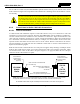

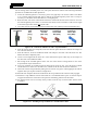

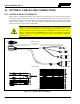
Table Of Contents
- 1 REGULATORY AND SAFETY INFORMATION
- 1.1 SAFETY SYMBOL CONVENTIONS
- 1.2 RF ENERGY EXPOSURE AWARENESS AND CONTROL INFORMATION FOR FCC OCCUPATIONAL USE REQUIREMENTS
- 1.3 COMPLIANCE WITH RF EXPOSURE STANDARDS
- 1.4 REGULATORY APPROVALS
- OCCUPATIONAL SAFETY GUIDELINES AND SAFETY TRAINING INFORMATION
- 1.6 COMMON HAZARDS
- 1.7 SAFE DRIVING RECOMMENDATIONS
- 1.8 OPERATING RULES AND REGULATIONS
- 1.9 OPERATING TIPS
- 2 SPECIFICATIONS
- 3 INTRODUCTION
- 4 UNPACKING AND CHECKING THE EQUIPMENT
- 5 PLANNING THE INSTALLATION
- 6 ANTENNA INSTALLATION
- 6.1 ANTENNA MOUNTING LOCATIONS
- 6.2 ANTENNA INSTALLATION PROCEDURES
- 7 FRONT-MOUNT RADIO INSTALLATION
- 8 REMOTE-MOUNT RADIO INSTALLATION
- 8.1 MOUNTING THE REMOTE-MOUNT RADIO
- 8.2 REMOTE-MOUNT RADIO’S DC POWER INSTALLATION
- 8.3 CONTROL HEAD INSTALLATION
- 8.3.1 General Information on the CH100 Control Head
- 8.3.2 General Information on the CH721 Control Head
- 8.3.3 Multi-Head Radio Installations
- 8.3.4 Control Head Mechanical Installation
- 8.3.5 Control Head-to-Radio CAN Cable Connections
- 8.3.6 Control Head Power Cable Installation
- 8.3.7 Using Vehicle Fuse and TTap Kit (Optional) Instead of Waterproof Inline Fuse Holder (Standard)
- 9 SPEAKER INSTALLATION
- 10 MICROPHONE ATTACHMENT
- 11 OPTIONAL CABLES AND CONNECTIONS
- 12 GPS NMEA-FORMATTED DATA CONNECTION
- 13 INITIAL POWER-UP TEST
- 14 PERFORMANCE TESTS
- 15 COMPLETE THE INSTALLATION
- 16 WARRANTY REGISTRATION
- 17 WARRANTY

14221-1200-4000, Rev. A
65
11. Obtain the 5-amp AGC-type fuse included with the cable, and install it into the fuse holder.
Do not share the control head’s fuse with any other device. Doing so can cause excess
current to flow through the fuse, causing it to blow unnecessarily.
The fuse for the control head’s red wire is rated at 5 amperes. The 3-amp fuse included
with the cable must not be used for fusing the control head’s main DC power. It fuses
the head’s white wire.
8.3.6.2 Connect DC Power Cable’s White Wire
A review of the information presented in Section 8.2.1 (page 51) may be beneficial at this time. As
required per the chosen power-up configuration, connect the white wire by following one of the three
procedures presented in the respective sub-section that follows.
8.3.6.2.1 Control Head and Radio Turn on with Vehicle’s Ignition Switch/Key
With this wiring configuration, the control head and radio automatically turn on and off with the vehicle’s
ignition switch/key. The white wire of the control head’s DC Power Cable is sometimes referred to as the
“white ignition switch wire” or the “ignition sense input wire.” In this configuration, the white wire
connects to a switched power source, typically identified as “Accessory” power, that switches on and off
with the vehicle’s ignition switch/key. When using this configuration, the on/off/volume control must be
left in the on position
. Otherwise, the radio will remain off when the ignition switch/key is on.
The white ignition sense wire must be connected to a fused power source that switches
from approximately zero volts to approximately +13.6 volts when the vehicle’s ignition
switch/key is turned from the OFF position to the ACCESSORY and RUN positions.
Use of a switched power source that is subject to voltage changes as a result of other
actions, such as opening a vehicle door, may result in undesirable radio power cycles.
1. Locate the vehicle’s switched ignition or “Accessory” power connection point that will be used for
the switched ignition 12-volt DC power source. This point is typically located at or near the vehicle’s
fuse panel. It may be necessary to consult the vehicle manufacturer’s wiring diagram.
2. Route the white wire of the control head’s DC Power Cable from the back of the head to the area near
this connection point. Protect the wire from possible chafing as necessary.
3. Obtain one of the yellow waterproof (HFB-type) fuse holders included with the control head’s DC
Power Cable.
4. Cut excess length from the white wire and splice the fuse holder into it, near the location of the
connection point.
5. Using an appropriate electrical terminal, connect the white wire to the switched power connection
point. An open-barrel spade terminal is included with the cable for this purpose, but another type of
terminal (not supplied) may be used as required.
6. Obtain the 3-amp AGC-type fuse included with the cable, and install it into the fuse holder.
7. Tie and stow all wiring as necessary so it remains out of the way of casual contact and wire chafe is
avoided.
NOTE
CAUTION
NOTE