
User Manual
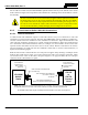

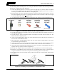

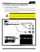
Table Of Contents
- 1 REGULATORY AND SAFETY INFORMATION
- 1.1 SAFETY SYMBOL CONVENTIONS
- 1.2 RF ENERGY EXPOSURE AWARENESS AND CONTROL INFORMATION FOR FCC OCCUPATIONAL USE REQUIREMENTS
- 1.3 COMPLIANCE WITH RF EXPOSURE STANDARDS
- 1.4 REGULATORY APPROVALS
- OCCUPATIONAL SAFETY GUIDELINES AND SAFETY TRAINING INFORMATION
- 1.6 COMMON HAZARDS
- 1.7 SAFE DRIVING RECOMMENDATIONS
- 1.8 OPERATING RULES AND REGULATIONS
- 1.9 OPERATING TIPS
- 2 SPECIFICATIONS
- 3 INTRODUCTION
- 4 UNPACKING AND CHECKING THE EQUIPMENT
- 5 PLANNING THE INSTALLATION
- 6 ANTENNA INSTALLATION
- 6.1 ANTENNA MOUNTING LOCATIONS
- 6.2 ANTENNA INSTALLATION PROCEDURES
- 7 FRONT-MOUNT RADIO INSTALLATION
- 8 REMOTE-MOUNT RADIO INSTALLATION
- 8.1 MOUNTING THE REMOTE-MOUNT RADIO
- 8.2 REMOTE-MOUNT RADIO’S DC POWER INSTALLATION
- 8.3 CONTROL HEAD INSTALLATION
- 8.3.1 General Information on the CH100 Control Head
- 8.3.2 General Information on the CH721 Control Head
- 8.3.3 Multi-Head Radio Installations
- 8.3.4 Control Head Mechanical Installation
- 8.3.5 Control Head-to-Radio CAN Cable Connections
- 8.3.6 Control Head Power Cable Installation
- 8.3.7 Using Vehicle Fuse and TTap Kit (Optional) Instead of Waterproof Inline Fuse Holder (Standard)
- 9 SPEAKER INSTALLATION
- 10 MICROPHONE ATTACHMENT
- 11 OPTIONAL CABLES AND CONNECTIONS
- 12 GPS NMEA-FORMATTED DATA CONNECTION
- 13 INITIAL POWER-UP TEST
- 14 PERFORMANCE TESTS
- 15 COMPLETE THE INSTALLATION
- 16 WARRANTY REGISTRATION
- 17 WARRANTY

14221-1200-4000, Rev. A
64
5. If not already mated, mate the other end of the CAN cable to one of the two CAN port connectors on
the rear panel of the radio.
6. Mate the second CAN terminator to the other CAN port connector on the rear panel of the radio. This
action makes the CAN termination at the radio-end of the CAN link.
7. Any necessary option/accessory cables from the back of the radio can also be routed with this wire
and cable within the vehicle’s interior (i.e., up to but not through the vehicle’s firewall). For example,
if the mobile radio installation must be interfaced to GPS, simultaneous routing of the related
interface cables along with the CAN cable can be time-saving. For GPS equipment cable part
numbers and cable installation procedures, refer to Section 12.
8. Loop, tie, and stow the cable(s) as necessary, leaving a service loop at the back of the radio and at the
back of the control head. Protect the entire length of the cable(s) and wire(s) from possible chafing.
8.3.6 Control Head Power Cable Installation
Plan the route of the control head’s DC Power Cable carefully. Do not route the cable where it will be
damaged by heat sources or by casual contact, and protect it from wire chafe per standard installation
methods. The following procedures are recommended:
8.3.6.1 Install DC Power Cable and Make Power and Ground Connections
1. Obtain the control head’s DC Power Cable from the respective installation kit. For the CH-100
control head, this is item 4 illustrated in Table 4-4. For the CH-721 control head, this is item 4
illustrated in Table 4-5.
2. Connect this cable to the large 3-pin connector at the rear of the head. Visually align the key and
gently push and turn the outer locking ring clockwise until it stops. A click will be sensed to confirm
proper mating.
3. At the back of the control head, locate a nearby section of vehicle chassis ground and strip this area of
any paint or dirt to expose a bare metal surface.
4. Cut the black wire of the control head’s DC Power Cable to the required length, plus a service loop of
at least six (6) inches, then strip it and crimp a ⅜-inch ring terminal to it. Two ring terminals of this
type are included with the cable.
5. Drill a hole, as necessary, and attach this ring terminal to chassis ground. Use stainless-steel self-
locking hardware (i.e., machine screws with washers and locking nuts) or other appropriate hardware
to ensure reliable terminal-to-metal contact. Tighten securely.
6. At the back of the control head, tie and stow the cable as necessary.
7. For the positive 12-volt DC main power source connection, route the cable’s red wire to the location
of an unswitched
12-volt DC power source, typically near the vehicle’s battery. Remove interior
panels, door kick panels, etc. Protect the wire from possible chafing as necessary. This is the control
head’s main DC power source.
8. Obtain one of the yellow waterproof (HFB-type) fuse holders included with the control head’s DC
Power Cable.
9. Cut excess length from the red wire and splice the fuse holder into it, near the location of the
unswitched 12-volt DC power source connection point. If necessary, a small amount of cable soap
may be used to help slip the wire through the small end of the fuse holder’s insulator.
10. Using an appropriate electrical terminal, connect the red wire to the unswitched DC power source. A
⅜-inch ring terminal is included with the cable for this purpose, but another terminal type (not
supplied) may be used if required.