
User Manual
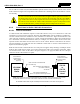

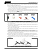

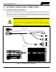
Table Of Contents
- 1 REGULATORY AND SAFETY INFORMATION
- 1.1 SAFETY SYMBOL CONVENTIONS
- 1.2 RF ENERGY EXPOSURE AWARENESS AND CONTROL INFORMATION FOR FCC OCCUPATIONAL USE REQUIREMENTS
- 1.3 COMPLIANCE WITH RF EXPOSURE STANDARDS
- 1.4 REGULATORY APPROVALS
- OCCUPATIONAL SAFETY GUIDELINES AND SAFETY TRAINING INFORMATION
- 1.6 COMMON HAZARDS
- 1.7 SAFE DRIVING RECOMMENDATIONS
- 1.8 OPERATING RULES AND REGULATIONS
- 1.9 OPERATING TIPS
- 2 SPECIFICATIONS
- 3 INTRODUCTION
- 4 UNPACKING AND CHECKING THE EQUIPMENT
- 5 PLANNING THE INSTALLATION
- 6 ANTENNA INSTALLATION
- 6.1 ANTENNA MOUNTING LOCATIONS
- 6.2 ANTENNA INSTALLATION PROCEDURES
- 7 FRONT-MOUNT RADIO INSTALLATION
- 8 REMOTE-MOUNT RADIO INSTALLATION
- 8.1 MOUNTING THE REMOTE-MOUNT RADIO
- 8.2 REMOTE-MOUNT RADIO’S DC POWER INSTALLATION
- 8.3 CONTROL HEAD INSTALLATION
- 8.3.1 General Information on the CH100 Control Head
- 8.3.2 General Information on the CH721 Control Head
- 8.3.3 Multi-Head Radio Installations
- 8.3.4 Control Head Mechanical Installation
- 8.3.5 Control Head-to-Radio CAN Cable Connections
- 8.3.6 Control Head Power Cable Installation
- 8.3.7 Using Vehicle Fuse and TTap Kit (Optional) Instead of Waterproof Inline Fuse Holder (Standard)
- 9 SPEAKER INSTALLATION
- 10 MICROPHONE ATTACHMENT
- 11 OPTIONAL CABLES AND CONNECTIONS
- 12 GPS NMEA-FORMATTED DATA CONNECTION
- 13 INITIAL POWER-UP TEST
- 14 PERFORMANCE TESTS
- 15 COMPLETE THE INSTALLATION
- 16 WARRANTY REGISTRATION
- 17 WARRANTY

14221-1200-4000, Rev. A
63
CAN Cable CA-009562-nnn
(where nnn specifies cable length in feet)
NOTE #2: The XG-100M mobile radio may be located in the middle of the CAN link.
For a 2-head installation, two CAN cables would connect directly to the two CAN
port connectors on the rear of the radio, and each control head would require a CAN
terminator. When the radio is in the middle of the CAN link, no CAN terminator is
required at the radio. The radio can support up to six (6) control heads.
CH-100
or
CH-721
Control
Head #1
(e.g., at main
operator location)
CAN Cable CA-009562-nnn
(where nnn specifies cable length in feet)
CAN Terminator CD-014027-001
(for control head end)
(See NOTE #3)
CAN
3-Pin CAN Port
Connectors on
Rear of Radio
(2 places)
CAN
CAN
XG-100M
Mobile
Radio
CAN
3-Pin CAN Port
Connectors on Rear
of Control Head
(2 places, this head)
CAN
CAN
CH-100
or
CH-721
Control
Head #2
(e.g., near rear of
vehicle)
CAN Terminator CD-014027-001
(for radio end)
NOTE #1: CH-100 and CH-721 control heads cannot
be
used together (i.e., mixed) within a radio installation.
NOTE #3: Right-Angle CAN Terminator MACDOS0010 also is available. This CAN
terminator can be used if the physical clearance at the back of the head is
insufficient for CAN Terminator CD-014027-001.
For Available CAN Cable Lengths and Respective Part Numbers, see Table 4-8 on page 31.
Figure 8-11: Typical CAN Link Connections for a Multi-Control Head Installation
8.3.5.2 Make CAN Link Terminations and Cable Connection
Follow this procedure for an installation which has only one control head. For a multi-control head
installation, refer to Figure 8-11 as necessary.
1. Obtain the two (2) CAN terminators, part number CD-014027-001, from the installation kit.
2. Mate one terminator to either one of the two smaller 3-pin CAN port connectors on the rear panel of
the control head. This action makes the CAN termination at the control head-end of the CAN link.
When mating any CAN connection (terminators and cables) to a rear panel connector,
visually align the ¾-moon-shaped keys of the connectors, and then gently push and
turn the outer locking ring of the plug (male) connector clockwise until it stops. A mild
click will be sensed to confirm proper mating. Without visual alignment as a guide, it
is possible with excessive force to mate the CAN connectors improperly. Damage to
the connector(s) may result. Therefore, visual alignment is recommended when mating
CAN connectors.
3. Per the procedure in section 8.2.2.2, the CAN cable was partially installed along with the red wire of
the radio’s DC Power Cable. Continue CAN cable installation by routing it to the area near the rear
of the control head.
4. Mate one end of the CAN cable to the other CAN port connector on the rear panel of the control head.
NOTE