
User Manual
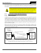

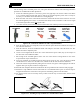

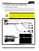
Table Of Contents
- 1 REGULATORY AND SAFETY INFORMATION
- 1.1 SAFETY SYMBOL CONVENTIONS
- 1.2 RF ENERGY EXPOSURE AWARENESS AND CONTROL INFORMATION FOR FCC OCCUPATIONAL USE REQUIREMENTS
- 1.3 COMPLIANCE WITH RF EXPOSURE STANDARDS
- 1.4 REGULATORY APPROVALS
- OCCUPATIONAL SAFETY GUIDELINES AND SAFETY TRAINING INFORMATION
- 1.6 COMMON HAZARDS
- 1.7 SAFE DRIVING RECOMMENDATIONS
- 1.8 OPERATING RULES AND REGULATIONS
- 1.9 OPERATING TIPS
- 2 SPECIFICATIONS
- 3 INTRODUCTION
- 4 UNPACKING AND CHECKING THE EQUIPMENT
- 5 PLANNING THE INSTALLATION
- 6 ANTENNA INSTALLATION
- 6.1 ANTENNA MOUNTING LOCATIONS
- 6.2 ANTENNA INSTALLATION PROCEDURES
- 7 FRONT-MOUNT RADIO INSTALLATION
- 8 REMOTE-MOUNT RADIO INSTALLATION
- 8.1 MOUNTING THE REMOTE-MOUNT RADIO
- 8.2 REMOTE-MOUNT RADIO’S DC POWER INSTALLATION
- 8.3 CONTROL HEAD INSTALLATION
- 8.3.1 General Information on the CH100 Control Head
- 8.3.2 General Information on the CH721 Control Head
- 8.3.3 Multi-Head Radio Installations
- 8.3.4 Control Head Mechanical Installation
- 8.3.5 Control Head-to-Radio CAN Cable Connections
- 8.3.6 Control Head Power Cable Installation
- 8.3.7 Using Vehicle Fuse and TTap Kit (Optional) Instead of Waterproof Inline Fuse Holder (Standard)
- 9 SPEAKER INSTALLATION
- 10 MICROPHONE ATTACHMENT
- 11 OPTIONAL CABLES AND CONNECTIONS
- 12 GPS NMEA-FORMATTED DATA CONNECTION
- 13 INITIAL POWER-UP TEST
- 14 PERFORMANCE TESTS
- 15 COMPLETE THE INSTALLATION
- 16 WARRANTY REGISTRATION
- 17 WARRANTY

14221-1200-4000, Rev. A
62
For the CH-721 control head, the MACDOS0012 pedestal attaches directly to the bottom of the control
head as shown in Figure 8-9. The pedestal is then mounted to a mounting surface located below or above
the assembly.
Be sure to use the #8-32 screws (with washers) supplied with the pedestal to attach it to
the head. These screws are the correct length for this application and they have SEMS-
type washers that will not easily separate from the screw. Installing the wrong screws or
the correct screws without the washers and/or the bracket in place could punch-out the
floor of the threaded holes, possibly damaging internal components of the head.
8.3.5 Control Head-to-Radio CAN Cable Connections
8.3.5.1 General Information
A remote-mount radio installation requires a CAN cable between every two “CAN devices” and CAN
terminators on each end of the CAN link. The Unity XG-100M mobile radio is considered a CAN device,
and each control head in the installation is also considered a CAN device. Figure 8-10 illustrates CAN
cable and CAN terminator connections for a single control head installation. Figure 8-11 illustrates this
for a multi-head control head installation where, for example, one control head is located at the main
operator location and another is located near the rear of the vehicle. Because CAN devices do not have
internal terminators, the CAN link must be terminated at both ends via external CAN terminators, as
depicted in the following figures.
Both the radio and the control head have two CAN ports to support “daisy-chaining” of multiple control
heads or other CAN devices. Figure 3-2 on page 19 shows the radio’s two CAN port connectors, which
are located near the center of the radio’s rear panel. Figure 8-7 on page 59 shows the two CAN port
connectors on the control head’s rear panel.
CAN Terminator CD-014027-001
(for radio end)
CH-100
or
CH-721
Control
Head
CAN Cable CA-009562-nnn
(where nnn specifies cable length in feet)
CAN Terminator CD-014027-001
(for control head end)
See NOTE.
CAN
3-Pin CAN Port
Connectors on
Rear of Radio
(2 places)
CAN
CAN
XG-100M
Mobile
Radio
CAN
3-Pin CAN Port
Connectors on Rear
of Control Head
(2 places)
NOTE: Right-Angle CAN Terminator MACDOS0010 also is available. This CAN terminator can be used if
the physical clearance at the back of the head is insufficient for CAN Terminator CD-014027-001.
For Available CAN Cable Lengths and Respective Part Numbers, see Table 4-8 on page 31.
Figure 8-10: CAN Link Connections for a Single Control Head Installation
CAUTION