
User Manual
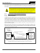


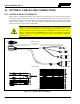
Table Of Contents
- 1 REGULATORY AND SAFETY INFORMATION
- 1.1 SAFETY SYMBOL CONVENTIONS
- 1.2 RF ENERGY EXPOSURE AWARENESS AND CONTROL INFORMATION FOR FCC OCCUPATIONAL USE REQUIREMENTS
- 1.3 COMPLIANCE WITH RF EXPOSURE STANDARDS
- 1.4 REGULATORY APPROVALS
- OCCUPATIONAL SAFETY GUIDELINES AND SAFETY TRAINING INFORMATION
- 1.6 COMMON HAZARDS
- 1.7 SAFE DRIVING RECOMMENDATIONS
- 1.8 OPERATING RULES AND REGULATIONS
- 1.9 OPERATING TIPS
- 2 SPECIFICATIONS
- 3 INTRODUCTION
- 4 UNPACKING AND CHECKING THE EQUIPMENT
- 5 PLANNING THE INSTALLATION
- 6 ANTENNA INSTALLATION
- 6.1 ANTENNA MOUNTING LOCATIONS
- 6.2 ANTENNA INSTALLATION PROCEDURES
- 7 FRONT-MOUNT RADIO INSTALLATION
- 8 REMOTE-MOUNT RADIO INSTALLATION
- 8.1 MOUNTING THE REMOTE-MOUNT RADIO
- 8.2 REMOTE-MOUNT RADIO’S DC POWER INSTALLATION
- 8.3 CONTROL HEAD INSTALLATION
- 8.3.1 General Information on the CH100 Control Head
- 8.3.2 General Information on the CH721 Control Head
- 8.3.3 Multi-Head Radio Installations
- 8.3.4 Control Head Mechanical Installation
- 8.3.5 Control Head-to-Radio CAN Cable Connections
- 8.3.6 Control Head Power Cable Installation
- 8.3.7 Using Vehicle Fuse and TTap Kit (Optional) Instead of Waterproof Inline Fuse Holder (Standard)
- 9 SPEAKER INSTALLATION
- 10 MICROPHONE ATTACHMENT
- 11 OPTIONAL CABLES AND CONNECTIONS
- 12 GPS NMEA-FORMATTED DATA CONNECTION
- 13 INITIAL POWER-UP TEST
- 14 PERFORMANCE TESTS
- 15 COMPLETE THE INSTALLATION
- 16 WARRANTY REGISTRATION
- 17 WARRANTY

14221-1200-4000, Rev. A
61
8.3.4.2 Using the Standard U-Shaped Mounting Bracket
If the standard U-shaped mounting bracket will be used to mount the control head, the following
mounting procedure is recommended.
1. Obtain the mounting bracket from the respective installation kit. For the CH-100 control head, this is
item 2, as illustrated Table 4-4 on page 25. For the CH-721 control head, this is item 2 as illustrated
in Table 4-5 on page 27.
2. Using the mounting bracket as a template, mark and drill mounting holes into the mounting surface as
required. The round and elliptical holes in the bracket’s vehicle mounting surface are symmetrical, so
forwards/backwards positioning is not important during this step. However, positioning is important
in the next step.
Before drilling holes and/or installing mounting screws, verify these operations will not
damage or interfere with any existing vehicle component (the fuel tank, a fuel line, the
transmission housing, existing vehicle wiring, electronic control modules, etc.). Always
check to see how far the mounting screws will extend beyond the mounting surface
prior to installation. Always deburr drilled holes before installing screws.
3. Postion the bracket at the mounting surface so the two round holes in its two side “ears” are nearest to
the normal location of the operator (typically towards the rear of the vehicle) and the two slotted holes
are furthest from
the normal location of the operator (typically towards the front of the vehicle).
4. Install and tighten the mounting screws. Screws for mounting the bracket to the mounting vehicle’s
surface are not included, as all installations differ. Self-threading screws are recommended. Use of
self-drilling screws may cause damage to some mounting surfaces, such as a plastic dash panel.
5. Verify the bracket is held firmly to the mounting surface. Firm mounting prevents unreasonable
vibration, which could damage the control head and/or cause its cable connections to loosen.
6. Slide the control head into the bracket, placing the two pegs protruding from its left and right sides
into the respective round holes in the bracket’s two side “ears.”
7. In each side “ear” of the mounting bracket, start a #8-32 hex-socket-head cap (Allen) head screw with
a lockwasher and a flat washer by inserting the screw through the slotted hole in the bracket and then
into the threaded hole in the side of the control head. This hardware is included with Mounting
Bracket Kit. The lockwasher should be adjacent to the screw head and the flat washer should be
adjacent to the bracket. Turn each screw clockwise as observed from the head of the screw.
8. The control head can be positioned at various angles for best display viewing at the normal position
of the operator. As necessary, tilt it on the pegs to a good position and tighten both screws using an
⅛-inch hex key (Allen) wrench until the control head is held firmly in place. Do not over-tighten.
8.3.4.3 Using the Optional Gimbal Mounting Pedestal
An optional Gimbal Mounting Pedestal, part number MACDOS0012, may be purchased separately to
replace the standard U-shaped mounting bracket.
For the CH-100 control head, the MACDOS0012 pedestal attaches to the bottom of the head with
Pedestal Mounting Kit 12099-1501-01. This kit includes Adapter Bracket 12099-0341-01 and stainless-
steel #8 hardware. The complete assembly is then mounted to a mounting surface located below the
assembly, such as the top of the vehicle’s dash panel.
CAUTION