
User Manual
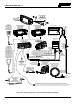
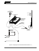
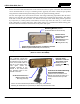
Table Of Contents
- 1 REGULATORY AND SAFETY INFORMATION
- 1.1 SAFETY SYMBOL CONVENTIONS
- 1.2 RF ENERGY EXPOSURE AWARENESS AND CONTROL INFORMATION FOR FCC OCCUPATIONAL USE REQUIREMENTS
- 1.3 COMPLIANCE WITH RF EXPOSURE STANDARDS
- 1.4 REGULATORY APPROVALS
- OCCUPATIONAL SAFETY GUIDELINES AND SAFETY TRAINING INFORMATION
- 1.6 COMMON HAZARDS
- 1.7 SAFE DRIVING RECOMMENDATIONS
- 1.8 OPERATING RULES AND REGULATIONS
- 1.9 OPERATING TIPS
- 2 SPECIFICATIONS
- 3 INTRODUCTION
- 4 UNPACKING AND CHECKING THE EQUIPMENT
- 5 PLANNING THE INSTALLATION
- 6 ANTENNA INSTALLATION
- 6.1 ANTENNA MOUNTING LOCATIONS
- 6.2 ANTENNA INSTALLATION PROCEDURES
- 7 FRONT-MOUNT RADIO INSTALLATION
- 8 REMOTE-MOUNT RADIO INSTALLATION
- 8.1 MOUNTING THE REMOTE-MOUNT RADIO
- 8.2 REMOTE-MOUNT RADIO’S DC POWER INSTALLATION
- 8.3 CONTROL HEAD INSTALLATION
- 8.3.1 General Information on the CH100 Control Head
- 8.3.2 General Information on the CH721 Control Head
- 8.3.3 Multi-Head Radio Installations
- 8.3.4 Control Head Mechanical Installation
- 8.3.5 Control Head-to-Radio CAN Cable Connections
- 8.3.6 Control Head Power Cable Installation
- 8.3.7 Using Vehicle Fuse and TTap Kit (Optional) Instead of Waterproof Inline Fuse Holder (Standard)
- 9 SPEAKER INSTALLATION
- 10 MICROPHONE ATTACHMENT
- 11 OPTIONAL CABLES AND CONNECTIONS
- 12 GPS NMEA-FORMATTED DATA CONNECTION
- 13 INITIAL POWER-UP TEST
- 14 PERFORMANCE TESTS
- 15 COMPLETE THE INSTALLATION
- 16 WARRANTY REGISTRATION
- 17 WARRANTY

14221-1200-4000, Rev. A
60
for the connectors/cables that must mate to the connectors on the rear panel of the head. The control head
can be mounted under or on top of a mounting surface (typically the vehicle’s dash) as space permits
using either the standard U-shaped mounting bracket or the optional mounting pedestal.
The size and weight of the control head necessitate less stringent mounting requirements than the radio.
However, like the radio, the control head must be mounted to a mechanically-rigid surface. The control
head must not vibrate when the vehicle is in motion and it must remain stable during normal operations
by an operator (i.e., button presses, knob rotation, excessive tugs on the mic cord, etc.). If the control
head is mounted to a plastic dash panel, either fender washers or a field-fabricated metal backing plate
should be utilized to mount the head’s bracket to the plastic dash panel.
Figure 8-8: Standard U-Shaped Control Head Mounting Bracket for CH-721 Control Head
(Kit Part Number KT-008608)
Figure 8-9: Optional Control Head Gimbal Mounting Pedestal (Part Number MACDOS0012)
Mounting Bracket (Shown
positioned above control head)
Control Head Gimbal
Mounting
Pedestal MACDOS0012
(Pedestal can be attached to the
bottom of the head (as shown) or it
can be attached to the top of the
head)
Bracket shown
attached to a CH-721
System model
control head (Head is
not
included with
Mounting Bracket Kit)
Pedestal shown
attached to a CH-721
Scan model control
head (Head is not
included with Moun
ting
Pedestal)
Socket-Head Cap (Allen) Screw, Lockwasher and Flat
Washer; 2 places each side (Included with kit)
#8-32 Pan-Head Screw; 4
places
(Included with
Mounting Pedestal)
For the CH-100 control head (not shown in this figure), use Pedestal
Mounting Kit 12099-1501-01 (not shown) to attach the pedestal to the head.
For a “hanging” control head
installation, the pedestal can
be attached to the top of the
head via threaded holes in
the top of the head’s case.
This figure shows the
pedestal attached to the
bottom of the control head
via
threaded holes in the
bottom of the case.