
User Manual
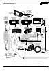
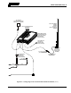
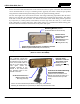
Table Of Contents
- 1 REGULATORY AND SAFETY INFORMATION
- 1.1 SAFETY SYMBOL CONVENTIONS
- 1.2 RF ENERGY EXPOSURE AWARENESS AND CONTROL INFORMATION FOR FCC OCCUPATIONAL USE REQUIREMENTS
- 1.3 COMPLIANCE WITH RF EXPOSURE STANDARDS
- 1.4 REGULATORY APPROVALS
- OCCUPATIONAL SAFETY GUIDELINES AND SAFETY TRAINING INFORMATION
- 1.6 COMMON HAZARDS
- 1.7 SAFE DRIVING RECOMMENDATIONS
- 1.8 OPERATING RULES AND REGULATIONS
- 1.9 OPERATING TIPS
- 2 SPECIFICATIONS
- 3 INTRODUCTION
- 4 UNPACKING AND CHECKING THE EQUIPMENT
- 5 PLANNING THE INSTALLATION
- 6 ANTENNA INSTALLATION
- 6.1 ANTENNA MOUNTING LOCATIONS
- 6.2 ANTENNA INSTALLATION PROCEDURES
- 7 FRONT-MOUNT RADIO INSTALLATION
- 8 REMOTE-MOUNT RADIO INSTALLATION
- 8.1 MOUNTING THE REMOTE-MOUNT RADIO
- 8.2 REMOTE-MOUNT RADIO’S DC POWER INSTALLATION
- 8.3 CONTROL HEAD INSTALLATION
- 8.3.1 General Information on the CH100 Control Head
- 8.3.2 General Information on the CH721 Control Head
- 8.3.3 Multi-Head Radio Installations
- 8.3.4 Control Head Mechanical Installation
- 8.3.5 Control Head-to-Radio CAN Cable Connections
- 8.3.6 Control Head Power Cable Installation
- 8.3.7 Using Vehicle Fuse and TTap Kit (Optional) Instead of Waterproof Inline Fuse Holder (Standard)
- 9 SPEAKER INSTALLATION
- 10 MICROPHONE ATTACHMENT
- 11 OPTIONAL CABLES AND CONNECTIONS
- 12 GPS NMEA-FORMATTED DATA CONNECTION
- 13 INITIAL POWER-UP TEST
- 14 PERFORMANCE TESTS
- 15 COMPLETE THE INSTALLATION
- 16 WARRANTY REGISTRATION
- 17 WARRANTY

14221-1200-4000, Rev. A
53
11. Apply an approved paint or rust-inhibitor over the remaining exposed bare metal surface and around
the ring terminal.
8.2.2.2 Red Wire, Main Fuse Holder Connection (Radio’s Main Power Wire), and
CAN Cable
In a typical vehicle installation, the majority of the CAN cable between the remote-mount radio and the
control head can be routed through the vehicle along with the 10-AWG red wire of the radio’s DC power
cable. This is a time-saving measure. Also, any necessary option/accessory cables from the back of the
radio can also be routed with this wire and cable within the vehicle’s interior (i.e., up to but not through
the vehicle’s firewall). The following installation procedure is recommended:
1. From the installation kit, obtain the CAN cable, part number CA-009562-030.
2. Remove interior panels, door kick panels, etc., as necessary to route the 10-AWG red wire and the
CAN cable from the area of the remote-mount radio (typically near the rear of the vehicle) to an area
near the vehicle’s firewall.
3. Route the red wire and the CAN cable through existing channels in the vehicle body to an area near
the vehicle’s firewall. Leave service loops at the rear of the radio. CAN cable installation is
completed per a later procedure in this manual (Section 8.3.5).
4. Continue installation of the 10-AWG red wire by routing it through the vehicle’s firewall to the
location of the vehicle’s battery (or its main DC bus bar or stud). Use an existing access hole in the
vehicle’s firewall if possible. Alternately, drill a new hole approximately ⅜-inch in diameter and
install a small rubber grommet to protect the wire from chafing on the hole’s sharp metal edge.
To prevent fumes from entering the passenger compartment, any
hole/grommet/wire combination in the vehicle’s firewall must be sealed with a
silicon-based sealer before completing the installation.
5. Protect the red wire and the CAN cable from possible chafing where necessary. Tie and stow them as
necessary.
Do not
install any wiring or fuse holder over or in the near vicinity of the vehicle’s
engine. Excessive engine heat can cause permanent damage to these components and
can lead to intermittent electrical connection to the battery.
Battery Ground WARNING: Before making connections to the battery’s positive
post, carefully disconnect the battery’s negative (ground) cable(s). This will
prevent tools or other metallic objects which come in contact with the battery’s
positive terminal from shorting to vehicle ground, causing sparks or even a fire or
an explosion! When disconnecting the negative cable(s), cover/insulate the positive
post(s) if it is not already so a tool cannot short between the posts. Some vehicles,
such as those with diesel engines have mor
e than one battery; in this case,
disconnect the negative cables at all batteries.
Radio and control head fuses should not be installed until all wiring is complete.
This will prevent the radio from powering up prematurely and/or causing an in-
rush of current that could lead to shorting of the battery, sparks, or even fire.
CAUTION
CAUTION
WARNING