
User Manual
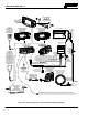
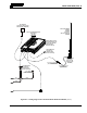
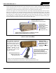
Table Of Contents
- 1 REGULATORY AND SAFETY INFORMATION
- 1.1 SAFETY SYMBOL CONVENTIONS
- 1.2 RF ENERGY EXPOSURE AWARENESS AND CONTROL INFORMATION FOR FCC OCCUPATIONAL USE REQUIREMENTS
- 1.3 COMPLIANCE WITH RF EXPOSURE STANDARDS
- 1.4 REGULATORY APPROVALS
- OCCUPATIONAL SAFETY GUIDELINES AND SAFETY TRAINING INFORMATION
- 1.6 COMMON HAZARDS
- 1.7 SAFE DRIVING RECOMMENDATIONS
- 1.8 OPERATING RULES AND REGULATIONS
- 1.9 OPERATING TIPS
- 2 SPECIFICATIONS
- 3 INTRODUCTION
- 4 UNPACKING AND CHECKING THE EQUIPMENT
- 5 PLANNING THE INSTALLATION
- 6 ANTENNA INSTALLATION
- 6.1 ANTENNA MOUNTING LOCATIONS
- 6.2 ANTENNA INSTALLATION PROCEDURES
- 7 FRONT-MOUNT RADIO INSTALLATION
- 8 REMOTE-MOUNT RADIO INSTALLATION
- 8.1 MOUNTING THE REMOTE-MOUNT RADIO
- 8.2 REMOTE-MOUNT RADIO’S DC POWER INSTALLATION
- 8.3 CONTROL HEAD INSTALLATION
- 8.3.1 General Information on the CH100 Control Head
- 8.3.2 General Information on the CH721 Control Head
- 8.3.3 Multi-Head Radio Installations
- 8.3.4 Control Head Mechanical Installation
- 8.3.5 Control Head-to-Radio CAN Cable Connections
- 8.3.6 Control Head Power Cable Installation
- 8.3.7 Using Vehicle Fuse and TTap Kit (Optional) Instead of Waterproof Inline Fuse Holder (Standard)
- 9 SPEAKER INSTALLATION
- 10 MICROPHONE ATTACHMENT
- 11 OPTIONAL CABLES AND CONNECTIONS
- 12 GPS NMEA-FORMATTED DATA CONNECTION
- 13 INITIAL POWER-UP TEST
- 14 PERFORMANCE TESTS
- 15 COMPLETE THE INSTALLATION
- 16 WARRANTY REGISTRATION
- 17 WARRANTY

14221-1200-4000, Rev. A
52
In all of the above cases, both the radio’s main DC power input (red wire) and the control head’s main
DC power input (also a red wire) must each be connected through an in-line fuse to unswitched vehicle
DC power. The red wire of the radio’s DC Power Cable must be connected to raw battery power (positive
battery terminal) via the supplied fuse. Likewise, the red wire of the control head’s DC Power Cable must
also be connected to unswitched vehicle DC power via another supplied fuse. The white ignition wire of
the radio’s
DC Power Cable is not used.
8.2.2 DC Power Cable, Main Fuse Holder, and CAN Cable Installation
The radio’s DC Power Cable has a 3-pin connector, a 20-foot red wire for the main power connection, a
4-foot black wire for the ground connection, and a 20-foot white wire which is not used. The cable is
supplied with waterproof fuse holders, three (3) AGC-type fuses, and non-insulated ring terminals.
Do not confuse the radio’s DC Power Cable which has a 10-AWG red wire with the
control head’s DC Power Cable which has a 12-AWG red wire. The radio requires
much more DC operating current than the control head. Therefore, it requires the
larger wire size of 10-AWG. The part number of the radio’s DC Power Cable is
CA-012365-001 and it has two wires which are 20-feet long.
In a typical vehicle installation, as a time saving measure, the majority of the length of the CAN cable
between the remote-mount radio and the control head can be routed together with the red wire of the
radio’s DC Power Cable. Also, any necessary option/accessory cables from the back of the radio can also
be routed with this wire and cable.
The following wire and cable installation procedures are recommended:
8.2.2.1 Black Wire Connection (Ground Wire)
1. Obtain the radio’s DC Power Cable, part number CA-012365-001.
2. Temporarily connect this cable to the radio by mating the cable’s 3-pin connector to the radio’s 3-pin
power connector. Locking the two connectors is not necessary at this time.
3. Prepare to connect the cable’s black wire to vehicle ground by locating an area of vehicle metal
within approximately two (2) feet of the radio. This surface must have a solid and stable connection
to vehicle ground. If not, add grounding strap(s) as necessary.
4. Verify the black wire has sufficient length to reach the ground point. If not, it can be extended by
splicing a 10-AWG wire to it. In this case, use approved wiring splicing methods and materials.
5. Strip the area of any paint or dirt to expose a bare metal surface, approximately ¾-inch square.
6. Drill a hole in the approximate center of the bare metal surface, and deburr it. A ⅜-inch non-insulated
ring terminal is supplied with the cable to make this ground connection. Therefore, hole diameter
should be appropriate for the utilized grounding screw/bolt size and type used to connect the ring
terminal to the bare metal surface. This hardware is not
supplied.
7. Cut the black wire to the required length plus some additional length for a service loop, then strip
insulation back approximately ¼-inch.
8. Crimp a ⅜-inch non-insulated ring terminal (supplied with the cable) to the end of the black wire.
9. Fully connect the cable to the radio by mating its 3-pin connector to the radio’s 3-pin power
connector as follows: Visually align the key and firmly push and turn the outer locking ring clockwise
until it stops. A click will be sensed to confirm proper mating.
10. Attach the ring terminal and black wire to the bare metal surface using stainless-steel self-locking
hardware (i.e., machine screws with washers and locking nuts) or other appropriate hardware to
ensure a reliable terminal-to-metal contact. Tighten securely.
CAUTION