
User Manual

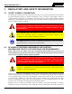


Table Of Contents
- 1 REGULATORY AND SAFETY INFORMATION
- 1.1 SAFETY SYMBOL CONVENTIONS
- 1.2 RF ENERGY EXPOSURE AWARENESS AND CONTROL INFORMATION FOR FCC OCCUPATIONAL USE REQUIREMENTS
- 1.3 COMPLIANCE WITH RF EXPOSURE STANDARDS
- 1.4 REGULATORY APPROVALS
- OCCUPATIONAL SAFETY GUIDELINES AND SAFETY TRAINING INFORMATION
- 1.6 COMMON HAZARDS
- 1.7 SAFE DRIVING RECOMMENDATIONS
- 1.8 OPERATING RULES AND REGULATIONS
- 1.9 OPERATING TIPS
- 2 SPECIFICATIONS
- 3 INTRODUCTION
- 4 UNPACKING AND CHECKING THE EQUIPMENT
- 5 PLANNING THE INSTALLATION
- 6 ANTENNA INSTALLATION
- 6.1 ANTENNA MOUNTING LOCATIONS
- 6.2 ANTENNA INSTALLATION PROCEDURES
- 7 FRONT-MOUNT RADIO INSTALLATION
- 8 REMOTE-MOUNT RADIO INSTALLATION
- 8.1 MOUNTING THE REMOTE-MOUNT RADIO
- 8.2 REMOTE-MOUNT RADIO’S DC POWER INSTALLATION
- 8.3 CONTROL HEAD INSTALLATION
- 8.3.1 General Information on the CH100 Control Head
- 8.3.2 General Information on the CH721 Control Head
- 8.3.3 Multi-Head Radio Installations
- 8.3.4 Control Head Mechanical Installation
- 8.3.5 Control Head-to-Radio CAN Cable Connections
- 8.3.6 Control Head Power Cable Installation
- 8.3.7 Using Vehicle Fuse and TTap Kit (Optional) Instead of Waterproof Inline Fuse Holder (Standard)
- 9 SPEAKER INSTALLATION
- 10 MICROPHONE ATTACHMENT
- 11 OPTIONAL CABLES AND CONNECTIONS
- 12 GPS NMEA-FORMATTED DATA CONNECTION
- 13 INITIAL POWER-UP TEST
- 14 PERFORMANCE TESTS
- 15 COMPLETE THE INSTALLATION
- 16 WARRANTY REGISTRATION
- 17 WARRANTY

14221-1200-4000, Rev. A
5
LIST OF TABLES
Page
Table 1-1: Recommended Minimum Safe Lateral Distance from a Transmitting Antenna Connected to a
Unity XG-100M Mobile Radio ...................................................................................................... 8
Table 4-1: Unity XG-100M Mobile Radio and CH-100/CH-721 Control Head Catalog and Part Numbers ...... 22
Table 4-2: Unity XG-100M Feature Packages .................................................................................................... 23
Table 4-3: Installation Kit XMZN6W for Front-Mount Unity XG-100M Mobile Radio ................................... 24
Table 4-4: Installation Kit XMZN9A for Remote-Mount Unity XG-100M Mobile Radio with CH-100
Control Head................................................................................................................................ 25
Table 4-5: Installation Kit XMZN7R for Remote-Mount Unity XG-100M Mobile Radio with CH-721
Control Head................................................................................................................................ 27
Table 4-6: CH-100 Control Head with Installation Components, Kit XMZN8Z ................................................ 29
Table 4-7: Additional Options and Accessories for the Unity XG-100M Mobile Radios ................................... 30
Table 4-8: Additional Options and Accessories for the CH-100 and CH-721 Control Heads ............................ 31
Table 11-1: Option Cable CA-012349-001 Interconnections .............................................................................. 71
Table 14-1: Required Test Equipment ................................................................................................................ 80
LIST OF FIGURES
Page
Figure 3-1: Front-Mount Unity XG-100M Mobile Radio with CH-100 Control Head ...................................... 17
Figure 3-2: Unity XG-100M Front-Mount and Remote-Mount Mobile Radios — Front and Rear Views ......... 19
Figure 6-1: Recommended Antenna Mounting Locations with Antenna Part Numbers ..................................... 34
Figure 6-2: Installing Standard ¾-Inch NMO Antenna Mount AN-125001-002 ................................................ 37
Figure 6-3: Installing Thick-Roof NMO Antenna Mount AN-125001-004 ........................................................ 37
Figure 6-4: Crimping Instructions for TNC RF Connector ................................................................................. 39
Figure 7-1: Front-Mount Mounting Bracket Kit KT101533V1 .......................................................................... 42
Figure 8-1: Remote-Mount Mounting Bracket Kit KT23117 ............................................................................. 50
Figure 8-2: Wiring Diagram for a Remote-Mount Radio Installation ................................................................. 54
Figure 8-3: CH-100 Control Head Front Panel ................................................................................................... 57
Figure 8-4: CH-100 Control Head Rear Panel (shown with Standard Mounting Bracket) ................................. 57
Figure 8-5: CH-721 Scan Model Control Head Front Panel ............................................................................... 58
Figure 8-6: CH-721 System Model Control Head Front Panel ........................................................................... 58
Figure 8-7: CH-721 Rear Panel (both control head models) ............................................................................... 59
Figure 8-8: Standard U-Shaped Control Head Mounting Bracket for CH-721 Control Head (Kit Part
Number KT-008608) ................................................................................................................... 60
Figure 8-9: Optional Control Head Gimbal Mounting Pedestal (Part Number MACDOS0012) ........................ 60
Figure 8-10: CAN Link Connections for a Single Control Head Installation ..................................................... 62
Figure 8-11: Typical CAN Link Connections for a Multi-Control Head Installation ......................................... 63
Figure 8-12: Contents of Vehicle Fuse and T-Tap Kit FS24473 ......................................................................... 67
Figure 8-13: Attaching T-Tap Terminals to a Switched Power Wire .................................................................. 67
Figure 11-1: Option Cable CA-012349-001 ........................................................................................................ 70
Figure 11-2: CH-721 Option Cable CA-011854-001 .......................................................................................... 74
Figure 11-3: Serial Data Cable CA-013671-020 ................................................................................................. 75
Figure 11-4: CH-721 Serial Programming Cable CA-104861 ............................................................................ 75
Figure 11-5: CH-721 Serial Programming Cable CA-103541-001 ..................................................................... 76
Figure 11-6: Speaker-Only Option Cable CA-012349-007 ................................................................................. 76
Figure 14-1: Wattmeter Connections for Antenna System Tests ........................................................................ 81