
User Manual
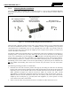
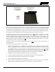
Table Of Contents
- 1 REGULATORY AND SAFETY INFORMATION
- 1.1 SAFETY SYMBOL CONVENTIONS
- 1.2 RF ENERGY EXPOSURE AWARENESS AND CONTROL INFORMATION FOR FCC OCCUPATIONAL USE REQUIREMENTS
- 1.3 COMPLIANCE WITH RF EXPOSURE STANDARDS
- 1.4 REGULATORY APPROVALS
- OCCUPATIONAL SAFETY GUIDELINES AND SAFETY TRAINING INFORMATION
- 1.6 COMMON HAZARDS
- 1.7 SAFE DRIVING RECOMMENDATIONS
- 1.8 OPERATING RULES AND REGULATIONS
- 1.9 OPERATING TIPS
- 2 SPECIFICATIONS
- 3 INTRODUCTION
- 4 UNPACKING AND CHECKING THE EQUIPMENT
- 5 PLANNING THE INSTALLATION
- 6 ANTENNA INSTALLATION
- 6.1 ANTENNA MOUNTING LOCATIONS
- 6.2 ANTENNA INSTALLATION PROCEDURES
- 7 FRONT-MOUNT RADIO INSTALLATION
- 8 REMOTE-MOUNT RADIO INSTALLATION
- 8.1 MOUNTING THE REMOTE-MOUNT RADIO
- 8.2 REMOTE-MOUNT RADIO’S DC POWER INSTALLATION
- 8.3 CONTROL HEAD INSTALLATION
- 8.3.1 General Information on the CH100 Control Head
- 8.3.2 General Information on the CH721 Control Head
- 8.3.3 Multi-Head Radio Installations
- 8.3.4 Control Head Mechanical Installation
- 8.3.5 Control Head-to-Radio CAN Cable Connections
- 8.3.6 Control Head Power Cable Installation
- 8.3.7 Using Vehicle Fuse and TTap Kit (Optional) Instead of Waterproof Inline Fuse Holder (Standard)
- 9 SPEAKER INSTALLATION
- 10 MICROPHONE ATTACHMENT
- 11 OPTIONAL CABLES AND CONNECTIONS
- 12 GPS NMEA-FORMATTED DATA CONNECTION
- 13 INITIAL POWER-UP TEST
- 14 PERFORMANCE TESTS
- 15 COMPLETE THE INSTALLATION
- 16 WARRANTY REGISTRATION
- 17 WARRANTY

14221-1200-4000, Rev. A
46
Do not install any wiring or fuse holder over or in the vicinity of the vehicle’s engine.
Excessive engine heat can cause permanent damage to these components and can lead
to intermittent electrical connection to the battery.
2. Obtain the orange waterproof (HFB type) fuse holder included with the DC Power Cable.
3. Observe and follow the previously presented Battery Ground WARNING!
4. Cut the red wire to the required length for connection to the battery’s positive (+) battery terminal (or
the main DC bus bar or stud).
5. Prepare to splice the fuse holder into the red wire by cutting it again, at approximately three (3) to six
(6) inches from the end.
6. Strip all three (3) wire ends back approximately ⅜-inch, place a fuse holder shell on each wire, and
securely crimp a fuse holder terminal to each wire end. Before crimping, verify fuse holder shells are
oriented in the correct directions (i.e., with each large end towards the wire end). If necessary, a small
amount of cable soap may be used to help slip the wire through the small end of the fuse holder’s
insulator.
7. Label this fuse holder and red wire appropriately (e.g., “XG-100M Radio Main Power: 20-AMP
FUSE”).
8. Do NOT install a fuse into the fuse holder at this time.
9. Crimp an appropriate electrical terminal to the short red wire. A corrosion-resistant ⅜-inch ring
terminal is included with the cable for this purpose, but another size corrosion-resistant terminal type
(not supplied) may be used if required.
10. Connect the ring terminal directly to the battery’s positive post (or if present, to a stud on the battery’s
main/non-switched power distribution terminal block).
A front-mount Unity XG-100M mobile radio installation may be connected to additional
control heads to form a multi-head radio installation. In this case, refer to Section 8.3 for
control head installation procedures.
The CH-100 control head cannot be mixed with the CH-721 control head within the same
multi-head radio installation. For example, a remote-mount CH-721 cannot be connected
to a front-mount XG-100M radio with a CH-100 control head.
7.2.2.3 White Wire Connection
A review of the information presented in Section 7.2.1 (page 44) may be beneficial at this time. As
required per the chosen power-up configuration, connect the white wire by following one of the three
procedures presented in the respective sub-section that follows.
7.2.2.3.1 Radio Turns On and Off with Vehicle’s Ignition Switch/Key
With this wiring configuration, the radio and its control head automatically turn on and off with the
vehicle’s ignition switch/key. The white wire is sometimes referred to as the “white ignition switch wire”
or the “ignition sense input wire.” In this configuration, the white wire connects to a switched power
source, typically identified as “Accessory” power, that switches on and off with the vehicle’s ignition
switch/key. When using this configuration, the on/off/volume control must be left in the on position
.
Otherwise, the radio will remain off when the ignition switch/key is on.
CAUTION
NOTE
NOTE