
User Manual
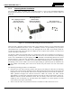
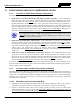
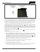
Table Of Contents
- 1 REGULATORY AND SAFETY INFORMATION
- 1.1 SAFETY SYMBOL CONVENTIONS
- 1.2 RF ENERGY EXPOSURE AWARENESS AND CONTROL INFORMATION FOR FCC OCCUPATIONAL USE REQUIREMENTS
- 1.3 COMPLIANCE WITH RF EXPOSURE STANDARDS
- 1.4 REGULATORY APPROVALS
- OCCUPATIONAL SAFETY GUIDELINES AND SAFETY TRAINING INFORMATION
- 1.6 COMMON HAZARDS
- 1.7 SAFE DRIVING RECOMMENDATIONS
- 1.8 OPERATING RULES AND REGULATIONS
- 1.9 OPERATING TIPS
- 2 SPECIFICATIONS
- 3 INTRODUCTION
- 4 UNPACKING AND CHECKING THE EQUIPMENT
- 5 PLANNING THE INSTALLATION
- 6 ANTENNA INSTALLATION
- 6.1 ANTENNA MOUNTING LOCATIONS
- 6.2 ANTENNA INSTALLATION PROCEDURES
- 7 FRONT-MOUNT RADIO INSTALLATION
- 8 REMOTE-MOUNT RADIO INSTALLATION
- 8.1 MOUNTING THE REMOTE-MOUNT RADIO
- 8.2 REMOTE-MOUNT RADIO’S DC POWER INSTALLATION
- 8.3 CONTROL HEAD INSTALLATION
- 8.3.1 General Information on the CH100 Control Head
- 8.3.2 General Information on the CH721 Control Head
- 8.3.3 Multi-Head Radio Installations
- 8.3.4 Control Head Mechanical Installation
- 8.3.5 Control Head-to-Radio CAN Cable Connections
- 8.3.6 Control Head Power Cable Installation
- 8.3.7 Using Vehicle Fuse and TTap Kit (Optional) Instead of Waterproof Inline Fuse Holder (Standard)
- 9 SPEAKER INSTALLATION
- 10 MICROPHONE ATTACHMENT
- 11 OPTIONAL CABLES AND CONNECTIONS
- 12 GPS NMEA-FORMATTED DATA CONNECTION
- 13 INITIAL POWER-UP TEST
- 14 PERFORMANCE TESTS
- 15 COMPLETE THE INSTALLATION
- 16 WARRANTY REGISTRATION
- 17 WARRANTY

14221-1200-4000, Rev. A
44
7.2 FRONT-MOUNT RADIO’S DC POWER INSTALLATION
7.2.1 Overview of On/Off Power Wiring Configurations
The following power wiring configurations are supported:
• Radio turns on and off automatically with vehicle’s ignition switch/key — This configuration
allows the on/off state of the vehicle’s ignition switch/key to control the on/off power state of the
radio. The white wire of the radio’s
DC Power Cable is connected to a fused switched power source,
typically identified as vehicle “Accessory” power. This source must switch on (up to positive (+)
battery voltage potential) when the vehicle’s ignition switch/key turns on, and it must switch off (to
near zero volts) when the ignition switch/key turns off. The required fuse rating is 3 amperes. When
using this configuration, the on/off/volume control must be left in the on position.
Otherwise, the
radio will remain off when the ignition switch/key is on.
In a front-mount Unity XG-100M radio installation, to fuse the white wire of the
radio’s DC Power Cable, a yellow waterproof (HFB type) fuse holder and a 3-amp
AGC fuse are included with the cable.
• Radio turns on and off with a manual switch — This configuration is used when, for example, the
radio has to remain on even when the ignition key must be removed from the vehicle and
a separate
on/off switch is acceptable. The white wire of the radio’s
DC Power Cable is connected to one side of
a manually-controlled switch, and the other side of this switch is connected to unswitched and fused
vehicle power. The required fuse rating is 3 amperes. When using this configuration, the
on/off/volume control must be left in the on position.
Otherwise, the radio will remain off when the
switch is on.
• Radio turns on with its on/off/volume control (“hot wired”) — This configuration allows radio
on/off power control only via its on/off/volume control. It may be desired if, for example, the radio
has to remain on even when the ignition key must be removed from the vehicle and a separate on/off
switch is not desired and/or not acceptable. The white wire of the radio’s
DC Power Cable must be
connected to unswitched and fused
vehicle power. The required fuse rating is 3 amperes.
In all of the above cases, the radio’s main DC power input (red wire) must be connected through an in-
line fuse to unswitched vehicle DC power. The red wire must be connected to raw battery power (positive
battery terminal) via the supplied fuse.
7.2.2 DC Power Cable and Main Fuse Holder Installation
The radio’s DC Power Cable has a 3-pin connector, a 20-foot red wire (for the main power connection), a
20-foot white wire (for the switched power source connection), and a 4-foot black wire (for the ground
connection). It is supplied with waterproof fuse holders, three (3) AGC-type fuses, and non-insulated ring
terminals. Only two of the three fuses are utilized in this application. The following installation
procedures are recommended:
7.2.2.1 Black Wire Connection (Ground Wire)
1. Temporarily connect the radio’s DC Power Cable to the radio by mating the cable’s 3-pin connector
to the radio’s 3-pin power connector. Locking the two connectors is not necessary at this time.
2. Prepare to connect the cable’s black wire to vehicle ground by locating an area of vehicle metal
within approximately two (2) feet of the radio. This surface must have a solid and stable connection
to vehicle ground. If not, add grounding strap(s) as necessary.
NOTE