
User Manual
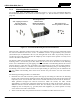
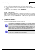
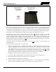
Table Of Contents
- 1 REGULATORY AND SAFETY INFORMATION
- 1.1 SAFETY SYMBOL CONVENTIONS
- 1.2 RF ENERGY EXPOSURE AWARENESS AND CONTROL INFORMATION FOR FCC OCCUPATIONAL USE REQUIREMENTS
- 1.3 COMPLIANCE WITH RF EXPOSURE STANDARDS
- 1.4 REGULATORY APPROVALS
- OCCUPATIONAL SAFETY GUIDELINES AND SAFETY TRAINING INFORMATION
- 1.6 COMMON HAZARDS
- 1.7 SAFE DRIVING RECOMMENDATIONS
- 1.8 OPERATING RULES AND REGULATIONS
- 1.9 OPERATING TIPS
- 2 SPECIFICATIONS
- 3 INTRODUCTION
- 4 UNPACKING AND CHECKING THE EQUIPMENT
- 5 PLANNING THE INSTALLATION
- 6 ANTENNA INSTALLATION
- 6.1 ANTENNA MOUNTING LOCATIONS
- 6.2 ANTENNA INSTALLATION PROCEDURES
- 7 FRONT-MOUNT RADIO INSTALLATION
- 8 REMOTE-MOUNT RADIO INSTALLATION
- 8.1 MOUNTING THE REMOTE-MOUNT RADIO
- 8.2 REMOTE-MOUNT RADIO’S DC POWER INSTALLATION
- 8.3 CONTROL HEAD INSTALLATION
- 8.3.1 General Information on the CH100 Control Head
- 8.3.2 General Information on the CH721 Control Head
- 8.3.3 Multi-Head Radio Installations
- 8.3.4 Control Head Mechanical Installation
- 8.3.5 Control Head-to-Radio CAN Cable Connections
- 8.3.6 Control Head Power Cable Installation
- 8.3.7 Using Vehicle Fuse and TTap Kit (Optional) Instead of Waterproof Inline Fuse Holder (Standard)
- 9 SPEAKER INSTALLATION
- 10 MICROPHONE ATTACHMENT
- 11 OPTIONAL CABLES AND CONNECTIONS
- 12 GPS NMEA-FORMATTED DATA CONNECTION
- 13 INITIAL POWER-UP TEST
- 14 PERFORMANCE TESTS
- 15 COMPLETE THE INSTALLATION
- 16 WARRANTY REGISTRATION
- 17 WARRANTY

14221-1200-4000, Rev. A
42
7.1.1 Mounting Bracket Installation
The front-mount Unity XG-100M radio’s mounting bracket is a part of the Front-Mount Mounting
Bracket Kit KT101533V1. Kit contents are shown in Figure 7-1. This kit is Item 1 listed in Table 4-3
(page 24).
Mounting Bracket
Self-Tapping Screws for FM101319V1
Securing Bracket (Marked KTB0310), M5 Hardware for
to Mounting Surface Ties and Grommet Securing Radio to Bracket
Figure 7-1: Front-Mount Mounting Bracket Kit KT101533V1
When selecting a mounting location for the radio, verify sufficient clearance can be maintained around
the radio for installation and service access. A minimum clearance of approximately four (4) inches
(10 centimeters) is recommended at the rear, left and right sides of the radio. As previously stated, the
area directly at the front of the radio must be completely clear of objects so the operator can easily access
and view the radio’s control head.
The bracket is both left-to-right and front-to-rear symmetrical. It has eleven (11) holes for securing it to a
mounting surface. At least four (4) of these holes must
be used to secure the bracket to the mounting
surface. Five 20-millimeter-long self-tapping screws are included in the Mounting Bracket Kit for this
purpose. However, some other type of hardware (not supplied) may be used, such as #10-32 stainless-
steel self-locking hardware (i.e., machine screws with washers and locking nuts), or self-drilling screws.
Self-drilling screws such as “TEK” screws do not require drilling of a pilot hole prior to installation. Do
not
use common self-threading sheet metal screws because they will loosen over time with vehicle
vibrations.
The following mounting procedure is recommended:
1. Determine the best radio-to-bracket position and angle by test-fitting the radio into the mounting
bracket at the selected vehicle mounting location. Slide the radio between the sides of the bracket and
temporarily secure it to the bracket with several of the M5 socket-head screws from the bracket kit.
When positioned straight and centered front-to-rear within the bracket, the radio extends
approximately 2.5 inches (6.4 centimeters) from the front and rear edges of the bracket. In the rear,
additional clearance must be included for cables. The area directly at the front of the radio must be
completely clear of all objects (e.g., gear shift, other radio equipment, etc.) so the operator can easily
access and view the radio’s control head.
2. At the rear of the radio, verify sufficient clearance is available for cables and service access.