
User Manual
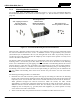
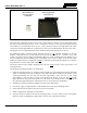
Table Of Contents
- 1 REGULATORY AND SAFETY INFORMATION
- 1.1 SAFETY SYMBOL CONVENTIONS
- 1.2 RF ENERGY EXPOSURE AWARENESS AND CONTROL INFORMATION FOR FCC OCCUPATIONAL USE REQUIREMENTS
- 1.3 COMPLIANCE WITH RF EXPOSURE STANDARDS
- 1.4 REGULATORY APPROVALS
- OCCUPATIONAL SAFETY GUIDELINES AND SAFETY TRAINING INFORMATION
- 1.6 COMMON HAZARDS
- 1.7 SAFE DRIVING RECOMMENDATIONS
- 1.8 OPERATING RULES AND REGULATIONS
- 1.9 OPERATING TIPS
- 2 SPECIFICATIONS
- 3 INTRODUCTION
- 4 UNPACKING AND CHECKING THE EQUIPMENT
- 5 PLANNING THE INSTALLATION
- 6 ANTENNA INSTALLATION
- 6.1 ANTENNA MOUNTING LOCATIONS
- 6.2 ANTENNA INSTALLATION PROCEDURES
- 7 FRONT-MOUNT RADIO INSTALLATION
- 8 REMOTE-MOUNT RADIO INSTALLATION
- 8.1 MOUNTING THE REMOTE-MOUNT RADIO
- 8.2 REMOTE-MOUNT RADIO’S DC POWER INSTALLATION
- 8.3 CONTROL HEAD INSTALLATION
- 8.3.1 General Information on the CH100 Control Head
- 8.3.2 General Information on the CH721 Control Head
- 8.3.3 Multi-Head Radio Installations
- 8.3.4 Control Head Mechanical Installation
- 8.3.5 Control Head-to-Radio CAN Cable Connections
- 8.3.6 Control Head Power Cable Installation
- 8.3.7 Using Vehicle Fuse and TTap Kit (Optional) Instead of Waterproof Inline Fuse Holder (Standard)
- 9 SPEAKER INSTALLATION
- 10 MICROPHONE ATTACHMENT
- 11 OPTIONAL CABLES AND CONNECTIONS
- 12 GPS NMEA-FORMATTED DATA CONNECTION
- 13 INITIAL POWER-UP TEST
- 14 PERFORMANCE TESTS
- 15 COMPLETE THE INSTALLATION
- 16 WARRANTY REGISTRATION
- 17 WARRANTY

14221-1200-4000, Rev. A
41
7 FRONT-MOUNT RADIO INSTALLATION
This section includes detailed instructions for mechanically installing and wiring a
front-mount Unity XG-100M mobile radio. For remote-mount Unity XG-100M mobile
radio installation procedures, refer to Section 8 which begins on page 49.
7.1 MOUNTING THE FRONT-MOUNT RADIO
The Mounting Bracket Kit for the front-mount Unity XG-100M mobile radio includes a heavy-gauge
steel U-shaped mounting bracket. The radio should be attached to a mounting surface using this bracket.
The bracket can be mounted above or below the radio. Kit contents are shown in Figure 7-1.
Both the radio and the mounting bracket have multiple holes in both sides for adjusting the radio within
the bracket. For the best viewing angle, the radio can be secured in the bracket in a tilted position. The
radio has six (6) threaded mounting holes, three (3) per side, and the mounting bracket has ten (10)
corresponding holes, five (5) per side. The radio must be secured to the bracket using at least four of the
six M5 socket-head screws included in the Mounting Bracket Kit (2 screws per side).
Typically, the radio is front-to-rear centered within the bracket. However, it can be front-to-rear offset by
approximately 2 inches (5.1 centimeters), if required. Also, the radio can be positioned straight in the
bracket (i.e., parallel with the bottom surface of the bracket), or it can be tilted up or down at an angle of
between approximately 10 to 20 degrees. When positioned straight and centered front-to-rear within the
bracket, the radio extends approximately 2.5 inches (6.4 centimeters) from the front and rear edges of the
bracket. In the rear, additional clearance must be included for cables. The area directly at the front of the
radio must be completely clear of all objects (e.g., gear shift, other radio equipment, etc.) so the operator
can easily access and view the radio’s control head. Two (2) screws per bracket/radio side are used when
the front-to-rear offset is employed.
The mounting bracket must be attached to a secure metal surface that meets or exceeds the minimum
1/16-inch-thick steel sheet metal requirement in accordance with the following
WARNING. For example,
it can be attached directly to the bottom of the dash if the gauge of the sheet metal is high and the surface
is firm and flat, or it can be attached to the transmission hump, etc., if a mounting wedge (not included) is
utilized. The front-mount Unity XG-100M radio weighs approximately 6 pounds (2.7 kilograms).
At a minimum, the mounting surface should be 16-gauge (approximately 1/16-inch
thick) steel sheet metal. Mounting to plastic or other material with low tensile and
shear strength is unsafe. A weak mount could turn the radio and its mounting
bracket into a dangerous projectile during a high-shock incident such as a motor
vehicle accident. If the selected mounting surface does not meet the minimum
16-gauge steel sheet metal requirement, the surface should be reinforced with a
metal backing plate (not supplied) or it should be reinforced using some other
approved mounting method.
In addition to improvin
g safety of the installation, firm mounting also prevents
unreasonable vibration that could damage the radio, adversely affect transceiver
performance and/or cause its cable connections to loosen. An improp
erly mounted
Unity XG-100M radio may experience degradation in the quality of voice and data
communications.
NOTE
WARNING
CAUTION