
User Manual
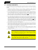
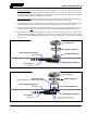
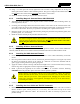
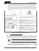
Table Of Contents
- 1 REGULATORY AND SAFETY INFORMATION
- 1.1 SAFETY SYMBOL CONVENTIONS
- 1.2 RF ENERGY EXPOSURE AWARENESS AND CONTROL INFORMATION FOR FCC OCCUPATIONAL USE REQUIREMENTS
- 1.3 COMPLIANCE WITH RF EXPOSURE STANDARDS
- 1.4 REGULATORY APPROVALS
- OCCUPATIONAL SAFETY GUIDELINES AND SAFETY TRAINING INFORMATION
- 1.6 COMMON HAZARDS
- 1.7 SAFE DRIVING RECOMMENDATIONS
- 1.8 OPERATING RULES AND REGULATIONS
- 1.9 OPERATING TIPS
- 2 SPECIFICATIONS
- 3 INTRODUCTION
- 4 UNPACKING AND CHECKING THE EQUIPMENT
- 5 PLANNING THE INSTALLATION
- 6 ANTENNA INSTALLATION
- 6.1 ANTENNA MOUNTING LOCATIONS
- 6.2 ANTENNA INSTALLATION PROCEDURES
- 7 FRONT-MOUNT RADIO INSTALLATION
- 8 REMOTE-MOUNT RADIO INSTALLATION
- 8.1 MOUNTING THE REMOTE-MOUNT RADIO
- 8.2 REMOTE-MOUNT RADIO’S DC POWER INSTALLATION
- 8.3 CONTROL HEAD INSTALLATION
- 8.3.1 General Information on the CH100 Control Head
- 8.3.2 General Information on the CH721 Control Head
- 8.3.3 Multi-Head Radio Installations
- 8.3.4 Control Head Mechanical Installation
- 8.3.5 Control Head-to-Radio CAN Cable Connections
- 8.3.6 Control Head Power Cable Installation
- 8.3.7 Using Vehicle Fuse and TTap Kit (Optional) Instead of Waterproof Inline Fuse Holder (Standard)
- 9 SPEAKER INSTALLATION
- 10 MICROPHONE ATTACHMENT
- 11 OPTIONAL CABLES AND CONNECTIONS
- 12 GPS NMEA-FORMATTED DATA CONNECTION
- 13 INITIAL POWER-UP TEST
- 14 PERFORMANCE TESTS
- 15 COMPLETE THE INSTALLATION
- 16 WARRANTY REGISTRATION
- 17 WARRANTY

14221-1200-4000, Rev. A
39
2. Using an appropriate crimp tool, crimp the supplied TNC RF connector to the end of the antenna
cable. For crimping instructions, see Figure 6-4 or the instructions supplied with antenna mount.
3. The antenna cable is connected to the radio’s TNC receptacle-type (female) RF connector per a
procedure presented later in this manual. The cable and its TNC connector must be protected from
damage, dirt, and/or metal shavings which may be generated during the mechanical and electrical
installation of the radio. Temporarily tying the connector and cable-end within a small plastic bag is
recommended.
Actual Size; Dimensions are in Inches
(VS-AN-025167-010 Rev. A)
Figure 6-4: Crimping Instructions for TNC RF Connector
6.2.6 Install GPS Antenna (If Required)
If the Unity XG-100M radio must provide GPS location information via its built-in GPS receiver, the
GPS receiver requires connection to an externally-mounted GPS antenna. The GPS antenna must be kept
at least six (6) inches away from any other antenna mounted on the vehicle and it must have at least six
inches of surface ground plane beneath it. The following antenna installation procedure is recommended:
A combination (“combo”) antenna kit includes a GPS antenna built into the base of the
mobile antenna. Refer to Table 4-7 on page 30 for available combo antennas.
1. After selecting a mounting location, refer to the antenna manufacturer’s mounting and testing
instructions for installation guidance. Install the antenna in accordance with these instructions. If
necessary, contact the Technical Assistance Center. See page 21 for TAC contact information. Do not
alter the GPS antenna cable length; tie and stow excess cable as necessary.
NOTE
1. Trim the end of the cable to the dimensions shown at the left, taking
care to not nick the cable’s inner conductor or its braid/shield.
2. Slip the crimp sleeve over the end of the cable, with its flanged-end
facing towards the end of the cable.
Place the contact onto the cable’s inner conductor. The end of the
con
tact and the cable’s inner dielectric must “butt square” together, as
shown to the left.
3.
While holding the contact tight against the dielectric, crimp the contact
to the inner conductor using an appropriate crimp tool.
4. Flair the cable’s outer braid/shield and then gently but firmly push the
contact (and cable end) into the connector housing until a gentle snap
is felt, indicating the contact is locked in place.
5. Slip the crimp sleeve in place, butting its flanged-end against the
connector housing.
6. Using an appropriate crimp tool, crimp the crimp sleeve securely to
the cable end and connector housing. When crimping, hold the
housing and sleeve firmly together, and to the cable end.