
User Manual
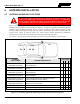
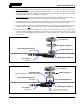
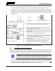
Table Of Contents
- 1 REGULATORY AND SAFETY INFORMATION
- 1.1 SAFETY SYMBOL CONVENTIONS
- 1.2 RF ENERGY EXPOSURE AWARENESS AND CONTROL INFORMATION FOR FCC OCCUPATIONAL USE REQUIREMENTS
- 1.3 COMPLIANCE WITH RF EXPOSURE STANDARDS
- 1.4 REGULATORY APPROVALS
- OCCUPATIONAL SAFETY GUIDELINES AND SAFETY TRAINING INFORMATION
- 1.6 COMMON HAZARDS
- 1.7 SAFE DRIVING RECOMMENDATIONS
- 1.8 OPERATING RULES AND REGULATIONS
- 1.9 OPERATING TIPS
- 2 SPECIFICATIONS
- 3 INTRODUCTION
- 4 UNPACKING AND CHECKING THE EQUIPMENT
- 5 PLANNING THE INSTALLATION
- 6 ANTENNA INSTALLATION
- 6.1 ANTENNA MOUNTING LOCATIONS
- 6.2 ANTENNA INSTALLATION PROCEDURES
- 7 FRONT-MOUNT RADIO INSTALLATION
- 8 REMOTE-MOUNT RADIO INSTALLATION
- 8.1 MOUNTING THE REMOTE-MOUNT RADIO
- 8.2 REMOTE-MOUNT RADIO’S DC POWER INSTALLATION
- 8.3 CONTROL HEAD INSTALLATION
- 8.3.1 General Information on the CH100 Control Head
- 8.3.2 General Information on the CH721 Control Head
- 8.3.3 Multi-Head Radio Installations
- 8.3.4 Control Head Mechanical Installation
- 8.3.5 Control Head-to-Radio CAN Cable Connections
- 8.3.6 Control Head Power Cable Installation
- 8.3.7 Using Vehicle Fuse and TTap Kit (Optional) Instead of Waterproof Inline Fuse Holder (Standard)
- 9 SPEAKER INSTALLATION
- 10 MICROPHONE ATTACHMENT
- 11 OPTIONAL CABLES AND CONNECTIONS
- 12 GPS NMEA-FORMATTED DATA CONNECTION
- 13 INITIAL POWER-UP TEST
- 14 PERFORMANCE TESTS
- 15 COMPLETE THE INSTALLATION
- 16 WARRANTY REGISTRATION
- 17 WARRANTY

14221-1200-4000, Rev. A
38
12. Using a
15
/
16
-inch open-end wrench, tighten the lock nut until it fully compresses the O-ring and
makes good contact with the vehicle mounting surface. The groove’s ridges on the bottom of the lock
nut must
make full contact with the unpainted metal surface of the vehicle.
13. Install the antenna element per the procedure in Section 6.2.4.
6.2.2 Installing Magnetic Antenna Mount AN-125001-008
1. Thoroughly clean the bottom of the magnetic mount and the selected vehicle mounting surface by
removing all dust, dirt, etc.
2. Carefully place the magnet mount onto the metal surface of the vehicle at the selected location. The
coax cable exiting the mount’s base should be orientated towards the point at which it will enter into
the interior of the vehicle. Do not try to reposition it by sliding it on a painted metal surface.
3. Route the mount’s coax cable to the radio location, passing it by the trunk lid’s perimeter gasket, door
perimeter gasket, etc., as necessary.
4. Install the antenna element per the procedure in Section 6.2.4.
To remove a magnetic antenna mount, hold it at the bottom of its base and tilt it at an
angle to release the magnetic attraction force. Do not pull on the mount’s coax cable.
Do not drag the mount across the mounting surface.
6.2.3 Installing All Other Antenna Mounts
For any other type of antenna mount not covered in the previous sections, such as GPS combination
antennas, install the mount in accordance with the installation instructions included with the mount.
6.2.4 Attaching the NMO Antenna Element
1. Clean the top surface of the NMO mount and the surface of the vehicle immediately around the
mount.
2. Place the gasket included with the antenna element (not pictured in Figure 6-2 or Figure 6-3) around
the mount and against the surface of the vehicle. If a lubricant or sealant was included with the
gasket, apply it to the gasket before placing the gasket.
3. Apply the antenna element to the top of the mount and tighten it in a clock-wise direction (as viewing
from the top). Use an appropriate wrench if required. Do not
over-tighten.
4. Install a placard (not supplied) on the vehicle’s dash panel, in accordance with the following
CAUTION. Place the placard in plain view of the vehicle operator’s position.
Before entering any automatic vehicle (“car”) wash equipment, remove the antenna
element from the antenna mount, and secure the element in a safe location inside the
vehicle. This will prevent the wash equipment from damaging the element and/or
mount. A
fter exiting the wash equipment, thoroughly dry the top of the mount before
re-installing the element.
5. Continue with the connection procedure presented in the next section.
6.2.5 Installing the Coax Cable and TNC RF Connector
1. Route the coax cable from the antenna mount to the location where the mobile radio will be installed.
Remove headliner panel, interior panels, etc., as necessary. The cable must be kept out of casual
contact from persons within the vehicle. Tie and stow the cable as necessary to protect it from
possible chafing.
CAUTION
CAUTION