
User Manual
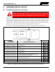
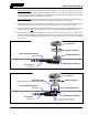
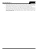
Table Of Contents
- 1 REGULATORY AND SAFETY INFORMATION
- 1.1 SAFETY SYMBOL CONVENTIONS
- 1.2 RF ENERGY EXPOSURE AWARENESS AND CONTROL INFORMATION FOR FCC OCCUPATIONAL USE REQUIREMENTS
- 1.3 COMPLIANCE WITH RF EXPOSURE STANDARDS
- 1.4 REGULATORY APPROVALS
- OCCUPATIONAL SAFETY GUIDELINES AND SAFETY TRAINING INFORMATION
- 1.6 COMMON HAZARDS
- 1.7 SAFE DRIVING RECOMMENDATIONS
- 1.8 OPERATING RULES AND REGULATIONS
- 1.9 OPERATING TIPS
- 2 SPECIFICATIONS
- 3 INTRODUCTION
- 4 UNPACKING AND CHECKING THE EQUIPMENT
- 5 PLANNING THE INSTALLATION
- 6 ANTENNA INSTALLATION
- 6.1 ANTENNA MOUNTING LOCATIONS
- 6.2 ANTENNA INSTALLATION PROCEDURES
- 7 FRONT-MOUNT RADIO INSTALLATION
- 8 REMOTE-MOUNT RADIO INSTALLATION
- 8.1 MOUNTING THE REMOTE-MOUNT RADIO
- 8.2 REMOTE-MOUNT RADIO’S DC POWER INSTALLATION
- 8.3 CONTROL HEAD INSTALLATION
- 8.3.1 General Information on the CH100 Control Head
- 8.3.2 General Information on the CH721 Control Head
- 8.3.3 Multi-Head Radio Installations
- 8.3.4 Control Head Mechanical Installation
- 8.3.5 Control Head-to-Radio CAN Cable Connections
- 8.3.6 Control Head Power Cable Installation
- 8.3.7 Using Vehicle Fuse and TTap Kit (Optional) Instead of Waterproof Inline Fuse Holder (Standard)
- 9 SPEAKER INSTALLATION
- 10 MICROPHONE ATTACHMENT
- 11 OPTIONAL CABLES AND CONNECTIONS
- 12 GPS NMEA-FORMATTED DATA CONNECTION
- 13 INITIAL POWER-UP TEST
- 14 PERFORMANCE TESTS
- 15 COMPLETE THE INSTALLATION
- 16 WARRANTY REGISTRATION
- 17 WARRANTY

14221-1200-4000, Rev. A
37
8. For a ¾-inch hole, feed the unterminated end of the mount’s coax cable into the hole from the top
surface of the vehicle until the mount’s bushing assembly is in position to drop into the hole. The
bushing should be tilted at a slight angle and fed into the hole. The threaded shank of the mount’s
bushing assembly will not fall through a ¾-inch hole.
For a ⅜ -inch hole
, feed the threaded shank of the mount’s bushing assembly into the hole from the
underside of the mounting surface. Hold it into position until the lock nut is installed.
9. If installing a thick-roof antenna mount (⅜-inch shank) into a ¾-inch hole, place the alignment ring
onto the threaded shank of the mount. This ring has an approximate ¾-inch outside diameter.
10. A tube of synthetic lubricant is included with the antenna mount. Apply this lubricant to the mount’s
rubber O-ring. Do not
get any lubricant on the center contact of the mount’s bushing assembly.
11. As illustrated in Figure 6-2 and Figure 6-3, add the O-ring (C) and lock nut (D) to the top of the
mount’s bushing assembly (A). With the O-ring in the groove in the underside of the lock nut, thread
the lock nut onto the bushing assembly. Be sure the O-ring remains in the groove before tightening
the lock nut.
Figure 6-2: Installing Standard ¾-Inch NMO Antenna Mount AN-125001-002
Figure 6-3: Installing Thick-Roof NMO Antenna Mount AN-125001-004
Coax Cable
(Partial)
Rubber O-Ring (C)
Vehicle Mounting Surface
(top side)
Bushing Assembly (A)
Lock Nut (D)
Coax Cable
(Partial)
Rubber O-Ring (C)
Vehicle Mounting Surface
(top side)
Bushing Assembly (A)
Lock Nut (D)
Threaded Shank (B)
Threaded Shank (B)
Alignment Ring
(Used only with ¾-inch mounting hole)
(Extensions shown to illustrate a
⅜-Inch hole vs. a ¾-inch hole.)