
User Manual
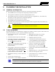
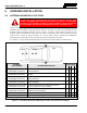

Table Of Contents
- 1 REGULATORY AND SAFETY INFORMATION
- 1.1 SAFETY SYMBOL CONVENTIONS
- 1.2 RF ENERGY EXPOSURE AWARENESS AND CONTROL INFORMATION FOR FCC OCCUPATIONAL USE REQUIREMENTS
- 1.3 COMPLIANCE WITH RF EXPOSURE STANDARDS
- 1.4 REGULATORY APPROVALS
- OCCUPATIONAL SAFETY GUIDELINES AND SAFETY TRAINING INFORMATION
- 1.6 COMMON HAZARDS
- 1.7 SAFE DRIVING RECOMMENDATIONS
- 1.8 OPERATING RULES AND REGULATIONS
- 1.9 OPERATING TIPS
- 2 SPECIFICATIONS
- 3 INTRODUCTION
- 4 UNPACKING AND CHECKING THE EQUIPMENT
- 5 PLANNING THE INSTALLATION
- 6 ANTENNA INSTALLATION
- 6.1 ANTENNA MOUNTING LOCATIONS
- 6.2 ANTENNA INSTALLATION PROCEDURES
- 7 FRONT-MOUNT RADIO INSTALLATION
- 8 REMOTE-MOUNT RADIO INSTALLATION
- 8.1 MOUNTING THE REMOTE-MOUNT RADIO
- 8.2 REMOTE-MOUNT RADIO’S DC POWER INSTALLATION
- 8.3 CONTROL HEAD INSTALLATION
- 8.3.1 General Information on the CH100 Control Head
- 8.3.2 General Information on the CH721 Control Head
- 8.3.3 Multi-Head Radio Installations
- 8.3.4 Control Head Mechanical Installation
- 8.3.5 Control Head-to-Radio CAN Cable Connections
- 8.3.6 Control Head Power Cable Installation
- 8.3.7 Using Vehicle Fuse and TTap Kit (Optional) Instead of Waterproof Inline Fuse Holder (Standard)
- 9 SPEAKER INSTALLATION
- 10 MICROPHONE ATTACHMENT
- 11 OPTIONAL CABLES AND CONNECTIONS
- 12 GPS NMEA-FORMATTED DATA CONNECTION
- 13 INITIAL POWER-UP TEST
- 14 PERFORMANCE TESTS
- 15 COMPLETE THE INSTALLATION
- 16 WARRANTY REGISTRATION
- 17 WARRANTY

14221-1200-4000, Rev. A
32
5 PLANNING THE INSTALLATION
5.1 GENERAL INFORMATION
Before starting, plan the installation carefully so it will meet the following requirements:
• The installation is safe for the operator and passengers within the vehicle.
• The equipment is installed away from the airbag deployment areas.
• The installation allows for convenient access by the operator, as applicable (i.e., the control head,
microphone, and other optional user-controlled equipment).
• The equipment is protected from water damage.
• The installation is neat and allows easy service access.
• The mobile radio is mounted in a location assuring the vehicle occupant’s safety and out of the way
of passengers and auto mechanics.
A professional radio installer should perform the installation!
5.2 TOOLS REQUIRED
The following tools are recommended to complete the installation. Where specific vendor names and
model or part numbers are given, equivalent substitutes may be used:
• Non-Insulated Crimp Tool: Thomas & Betts
WT-111-M
• Phillips-Head Screwdrivers, #1 and #2
• Flat-Blade Screwdrivers, #1 and #2
• Insulated Terminal Crimp Tool: Klein 1005
• 4-Millimeter Hex Key Wrench
• Fuse Holder Crimp Tool: Thomas & Betts –
WT-112M or
California Terminal Products
No. 1250 or
Channelock No. 909
• ⅛-Inch Hex Key Wrench (Allen Wrench)
•
5
/
16
-Inch Combination or Open-End Wrench
(Only Needed for GPS Receiver Option)
• 3-Blade Coax Cable Stripper for RG-58 Cable
similar to Tyco Electronics 1490490-1
(includes blades)
• ¾-Inch or ⅜-Inch Hole Saw with Depth
Protection: ¾-Inch = Ripley HSK 19 or
Antenex HS34; ⅜-Inch = Antenex HS38
• Ratcheting Hex-Crimp Tool for 50-Ohm TNC
and BNC RF Connectors and RG-58 Cable
similar to Tyco Electronics 58433-2 (includes
Crimper 354940-1 and Die Set 58436-1) or
Emerson Network Power 24-9960P
• Clutch-Type Cordless Drill with Drill Bits and
Driver Bits
• Deburring Tool (for ⅜-inch and smaller holes)
• Flush-Cut and Large Wire Cutters
• Non-Metallic Fish Tape, 25-Foot: Klein-Lite
50156
• Various Fasteners (e.g., machine screws and
nuts, Tek screws, etc.)
• Various Socket and Driver Sets
• Tie Wraps: Nylon, 6-inches or larger
•
Soft-Jaw Pliers: Tessco 450520 or equivalent
A separate list of test equipment is included in Section 14.1 on page 80.
CAUTION
NOTE