
User Manual
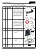
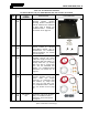
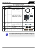
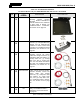
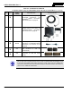
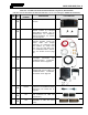
Table Of Contents
- 1 REGULATORY AND SAFETY INFORMATION
- 1.1 SAFETY SYMBOL CONVENTIONS
- 1.2 RF ENERGY EXPOSURE AWARENESS AND CONTROL INFORMATION FOR FCC OCCUPATIONAL USE REQUIREMENTS
- 1.3 COMPLIANCE WITH RF EXPOSURE STANDARDS
- 1.4 REGULATORY APPROVALS
- OCCUPATIONAL SAFETY GUIDELINES AND SAFETY TRAINING INFORMATION
- 1.6 COMMON HAZARDS
- 1.7 SAFE DRIVING RECOMMENDATIONS
- 1.8 OPERATING RULES AND REGULATIONS
- 1.9 OPERATING TIPS
- 2 SPECIFICATIONS
- 3 INTRODUCTION
- 4 UNPACKING AND CHECKING THE EQUIPMENT
- 5 PLANNING THE INSTALLATION
- 6 ANTENNA INSTALLATION
- 6.1 ANTENNA MOUNTING LOCATIONS
- 6.2 ANTENNA INSTALLATION PROCEDURES
- 7 FRONT-MOUNT RADIO INSTALLATION
- 8 REMOTE-MOUNT RADIO INSTALLATION
- 8.1 MOUNTING THE REMOTE-MOUNT RADIO
- 8.2 REMOTE-MOUNT RADIO’S DC POWER INSTALLATION
- 8.3 CONTROL HEAD INSTALLATION
- 8.3.1 General Information on the CH100 Control Head
- 8.3.2 General Information on the CH721 Control Head
- 8.3.3 Multi-Head Radio Installations
- 8.3.4 Control Head Mechanical Installation
- 8.3.5 Control Head-to-Radio CAN Cable Connections
- 8.3.6 Control Head Power Cable Installation
- 8.3.7 Using Vehicle Fuse and TTap Kit (Optional) Instead of Waterproof Inline Fuse Holder (Standard)
- 9 SPEAKER INSTALLATION
- 10 MICROPHONE ATTACHMENT
- 11 OPTIONAL CABLES AND CONNECTIONS
- 12 GPS NMEA-FORMATTED DATA CONNECTION
- 13 INITIAL POWER-UP TEST
- 14 PERFORMANCE TESTS
- 15 COMPLETE THE INSTALLATION
- 16 WARRANTY REGISTRATION
- 17 WARRANTY

14221-1200-4000, Rev. A
24
Table 4-3: Installation Kit XMZN6W
for Front-Mount Unity XG-100M Mobile Radio
ITEM QTY.
PART
NUMBER
DESCRIPTION ILLUSTRATION
1
1
KT101533V1
Kit, Front-Mount Mounting Bracket.
Includes Mounting Bracket
FM101319V1 (marked KTB0310),
M5 stainless-
steel hardware to
attach radio to bracket, self-tapping
hardware to attach bracket to
mounting surface, ½-
inch rubber
grommet, and 7-inch cable ties.
For installation-related information,
see Section 7.1 on page 41.
2
1
CA-012365-
001
Cable, DC Power. Includes
10-AWG, 20-Foot DC Power Cable
with straight connector, (2)
waterproof HFB fuse holders, (1)
20-amp AGC fuse, (1) 15-amp
AGC fuse and (1) 3-
amp AGC
fuse. See CAUTION that follows.
For installation-related information,
see Section 7.2 on page 44.
3
2
CD-014027-
001
Terminator, CAN; 3-Pin, Straight
Body. See Section 7.3 on page 48.
4
1
LS102824V10
Speaker, External Mobile; 20-Watt
(with 4.6-foot cable). See Section
9.1 on page 68.
5
1
CA-012349-
001
Cable, Option. For installation-
related information, s
ee Section
11.1 (page 70).
6
1
FM-104859-
001
Cap, Waterproof (For covering
Radio’s DB-
9 serial port
connector).