
User Manual

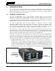
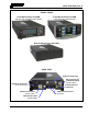
Table Of Contents
- 1 REGULATORY AND SAFETY INFORMATION
- 1.1 SAFETY SYMBOL CONVENTIONS
- 1.2 RF ENERGY EXPOSURE AWARENESS AND CONTROL INFORMATION FOR FCC OCCUPATIONAL USE REQUIREMENTS
- 1.3 COMPLIANCE WITH RF EXPOSURE STANDARDS
- 1.4 REGULATORY APPROVALS
- OCCUPATIONAL SAFETY GUIDELINES AND SAFETY TRAINING INFORMATION
- 1.6 COMMON HAZARDS
- 1.7 SAFE DRIVING RECOMMENDATIONS
- 1.8 OPERATING RULES AND REGULATIONS
- 1.9 OPERATING TIPS
- 2 SPECIFICATIONS
- 3 INTRODUCTION
- 4 UNPACKING AND CHECKING THE EQUIPMENT
- 5 PLANNING THE INSTALLATION
- 6 ANTENNA INSTALLATION
- 6.1 ANTENNA MOUNTING LOCATIONS
- 6.2 ANTENNA INSTALLATION PROCEDURES
- 7 FRONT-MOUNT RADIO INSTALLATION
- 8 REMOTE-MOUNT RADIO INSTALLATION
- 8.1 MOUNTING THE REMOTE-MOUNT RADIO
- 8.2 REMOTE-MOUNT RADIO’S DC POWER INSTALLATION
- 8.3 CONTROL HEAD INSTALLATION
- 8.3.1 General Information on the CH100 Control Head
- 8.3.2 General Information on the CH721 Control Head
- 8.3.3 Multi-Head Radio Installations
- 8.3.4 Control Head Mechanical Installation
- 8.3.5 Control Head-to-Radio CAN Cable Connections
- 8.3.6 Control Head Power Cable Installation
- 8.3.7 Using Vehicle Fuse and TTap Kit (Optional) Instead of Waterproof Inline Fuse Holder (Standard)
- 9 SPEAKER INSTALLATION
- 10 MICROPHONE ATTACHMENT
- 11 OPTIONAL CABLES AND CONNECTIONS
- 12 GPS NMEA-FORMATTED DATA CONNECTION
- 13 INITIAL POWER-UP TEST
- 14 PERFORMANCE TESTS
- 15 COMPLETE THE INSTALLATION
- 16 WARRANTY REGISTRATION
- 17 WARRANTY

14221-1200-4000, Rev. A
18
and a microphone connector.
• CH-721 Scan Model Control Head—This head features a large 3-line graphical vacuum-fluorescent
display and easy-to-use front panel controls, including three (3) large menu-related buttons. Figure
8-5 on page 58 details all front panel components.
• CH-721 System Model Control Head— Figure 3-2 on page 19 illustrates the CH-721 System model
control head in a front-mount configuration. This head is very similar to the CH-721 Scan model
control head. It has an identical 3-line graphical vacuum-fluorescent display. Also, front panel
controls are identical to those on the Scan model control head with the exception of the 12-key
keypad and smaller menu-related buttons. The 12-key numeric keypad provides Dual-Tone Multi-
Frequency (DTMF) functionality and advanced operator system/group selection control via the
control head’s front panel. Figure 8-6 on page 58 details all front panel components.
All three (3) control heads feature a large easy-to-use volume/on/off rotary control and a rotary
system/group/channel selection control. In addition, each head also has a front panel microphone
connector, and an internal high-power audio amplifier to drive an externally-connected speaker. All heads
used with remote-mount radios have rear panel connectors for DC power, CAN link, speaker audio
output, serial port, and optional accessory connections.
In a remote-mount radio configuration, a Controller Area Network (CAN) cable provides the radio-to-
head connection. Between the radio and control head(s), the CAN link carries digitized microphone and
speaker audio, controlling data such as button presses and radio messages, and user data such as that for a
mobile data terminal connected to the serial port of the radio or control head. The CAN link is basically
2-wire (with shield ground) daisy-chained high-speed serial data link. For proper operation, the CAN link
must be terminated on each end with a simple resistive-type terminator.
The CAN link is also used to interconnect additional control heads to a radio in a multi-head installation.
In a multi-head mobile radio installation, more than one control head is utilized with a radio. A multi-
head installation may be required in a vehicle such as a fire truck or any large vehicle where more than
one operator position must support radio use. For example, a ladder fire truck could have a front-mount
XG-100M mobile radio mounted under the truck’s dash panel and a remote-mount control head mounted
at the ladder operator’s position. Each control head in a multi-head installation is equipped with an
external speaker, a microphone, and optionally-connected equipment. Multi-head installations provide
other benefits such as intercom functionality. The XG-100M mobile radio can support up to six (6)
control heads.
The CH-100 control head cannot be mixed with the CH-721 control head within the same
multi-head radio installation. For example, a remote-mount CH-721 cannot be connected
to a front-mount XG-100M radio with a CH-100 control head.
The radio and control head must be powered by an external +13.6-volt (nominal) DC power source. In
mobile applications, the motor vehicle’s electrical system is utilized as the source of DC power. In a
remote-mount radio installation, the control head(s) connected to the radio is also powered by the same
DC power source, but separately fused. When the control head is powered-up by the operator, it “wakes
up” the radio by transmitting data to the radio via the CAN link.
The radio provides half-duplex voice and data communications. Voice communications are accomplished
via a “push-to-talk” (PTT) type microphone and an external speaker connected to the control head. When
a control head is employed in a remote-mount mobile radio installation, an audio amplifier in the head
drives the speaker.
NOTE