
User Manual


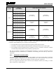
Table Of Contents
- 1. SAFETY SYMBOL CONVENTIONS
- 2. RF ENERGY EXPOSURE INFORMATION
- 3. OPERATION SAFETY RECOMMENDATIONS
- 4. OPERATING RULES AND REGULATIONS
- 5. INTRODUCTION
- 6. BASIC OPERATION
- 6.1 PROGRAMMING
- 6.2 XG-100M CONTROLS
- 6.3 DISPLAY
- 6.4 STATUS MESSAGES
- 6.5 ALERT TONES
- 6.6 BEFORE FIRST USE
- 6.7 POWER ON AND SET VOLUME
- 6.8 TURN ENCRYPTION ON OR OFF
- 6.9 USER INTERFACE PRIVILEGE LEVEL
- 6.10 SELECT CHANNEL USING MENUS
- 6.11 SELECT ZONE/SYSTEM USING MENUS
- 6.12 USE TALKAROUND TO BYPASS REPEATER (ANALOG AND P25 CONVENTIONAL)
- 6.13 INDIVIDUAL CALLS
- 6.14 SELECT A NEW TALKGROUP
- 6.15 SCAN OPERATION
- 6.16 VIEW GPS INFORMATION
- 6.17 EMERGENCY OPERATION
- 6.18 ENCRYPTION BAR
- 6.19 LIGHTS AND SIRENS
- 6.20 PUBLIC ADDRESS (PA)
- 6.21 SHORTCUT MENU
- 7. ADVANCED OPERATIONS
- 7.1 CREATE KEYS
- 7.2 LOAD KEYS
- 7.3 LOAD KEYGROUPS
- 7.4 ZEROIZE ALL FROM RADIO
- 7.5 ZEROIZE KEYS USING KVL 3000 PLUS
- 7.6 ZEROIZE KEYGROUPS USING KVL 3000 PLUS
- 7.7 ZEROIZE ALL FROM KVL 3000 PLUS
- 7.8 GLOBAL ENCRYPTION
- 7.9 SELECT KEYSET
- 7.10 OTAR CONFIGURATION
- 7.11 ACTIVATE/VIEW MISSION PLAN
- 7.12 CH INFORMATION MENU
- 7.13 EDIT CHANNEL (ANALOG AND P25 CONVENTIONAL ONLY)
- 7.14 SETTINGS MENU
- 7.15 SET UP SCAN
- 7.16 MESSAGE MENU
- 7.17 UTILITIES MENU
- 8. REFERENCE
- 9. GLOSSARY
- 10. BASIC TROUBLESHOOTING
- 11. TECHNICAL ASSISTANCE
- 12. WARRANTY

14221-1200-2010
9
RF BAND
ANTENNA
PART NUMBERS
RECOMMENDED MINIMUM LATERAL HUMAN BODY DISTANCE
FROM TRANSMITTING ANTENNA
CONTROLLED ENVIRONMENT UNCONTROLLED ENVIRONMENT
UHF
AN-125001-002 (mount) with
12099-0310-01 (element)
24.4 inches
(62 centimeters)
54.3 inches
(138 centimeters)
AN-125001-004 (mount) with
12099-0310-01 (element)
AN-125001-006 (mount) with
12099-0310-01 (element)
AN-125001-008 (mount) with
12099-0310-01 (element)
AN-125001-002 (mount) with
12099-0330-01 (element)
33.9 inches
86 cm
75.6 inches
192 cm
AN-125001-004 (mount) with
12099-0330-01 (element)
700/800 MHz
AN-125001-002 (mount) with
12099-0310-01 (element)
7.9 inches
(20 centimeters)
19.7 inches
(50 centimeters)
AN-125001-004 (mount) with
12099-0310-01 (element)
AN-125001-006 (mount) with
12099-0310-01 (element)
AN-125001-008 (mount) with
12099-0310-01 (element)
AN-125001-002 (mount) with
12099-0330-01 (element)
7.9 inches
(20 centimeters)
24 inches
(61 centimeters)
AN-125001-004 (mount) with
12099-0330-01 (element)
* Install the radio’s antenna in the center of the vehicle’s roof. These mobile antenna installation guidelines
are limited to metal body motor vehicles or vehicles with appropriate ground planes. The antenna
installation should additionally be in accordance with the following:
• The requirements of the antenna manufacturer/supplier included with the antenna.
• Instructions in the Unity Radio Installation Manual, including minimum antenna cable lengths.
• The installation manual providing specific information of how to install the antennas to facilitate
recommended operating distances to all potentially exposed persons.
Use only the Harris Corporation approved/supplied antenna(s) or approved replacement antenna.
Unauthorized antennas, modifications, or attachments could damage the radio and may violate FCC
regulations.
2.2.2 APPROVED ACCESSORIES
This radio has been tested and meets the FCC RF guidelines when used with the Harris Corporation
accessories supplied or designated for use with this product. Use of other accessories may not ensure
compliance with the FCC’s RF exposure guidelines, and may violate FCC regulations.
For a list of approved accessories refer to Section 8.2, the Products and Services Catalog, or contact
Harris Corporation at 1-800-368-3277.