EFFECTIVE: November 1, 2013 THEATRICAL CHAIN HOIST TNER SERIES 1/2 Ton through 2 Ton Capacity Code, Lot and Serial Number This equipment should not be installed, operated, or maintained by any person who has not read and understood all the contents of this manual. Failure to read and comply with the contents of this manual can result in serious bodily injury or death, and/or property damage.
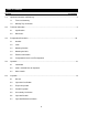
Table of Contents Section 1.0 2.0 3.0 4.0 5.0 Page Number Important Information and Warnings ……………………………………………………………………… 4 1.1 Terms and Summary 1.2 Warning Tags and Labels Technical Information…………………………………………………………………………….…………. 8 2.1 Specifications 2.2 Dimensions Preoperational Procedures ………………………………………………………………………………10 3.1 Gearbox 3.2 Chain 3.3 Mounting Location 3.4 Mounting the Hoist 3.5 Electrical Connections 3.
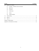
Section 6.0 Page Number Maintenance & Handling …………………………………………………………………………………. 26 6.1 Lubrication – Load Chain, Hooks and Gearbox 6.2 Motor Brake 6.3 Load Chain 6.4 Friction Clutch 6.5 Storage 6.6 Outdoor Installation 7.0 Troubleshooting …………………………………………………………………………………………… 32 8.0 Warranty …………………………………………………………………………………………………… 35 9.0 Parts List …………………………………………………………………………………………………… 37 Appendix A: Wiring Diagram …………………………...
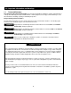
1.0 Important Information and Warnings 1.1 Terms and Summary This manual provides important information for personnel involved with the installation, operation and maintenance of this product. Although you may be familiar with this or similar equipment, it is strongly recommended that you read this manual before installing, operating or maintaining the product. Danger, Warning, Caution and Notice Throughout this manual there are steps and procedures that can present hazardous situations.
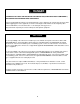
Equipment described herein is not designed for and MUST NOT be used for lifting, supporting, or transporting people, or for lifting or supporting loads over people. Equipment described herein should not be used in conjunction with other equipment unless necessary and/or required safety devices applicable to the system, crane, or application are installed by the system designer, system manufacturer, crane manufacturer, installer, or user.
HAZARDOUS VOLTAGES ARE PRESENT IN THE CONTROL BOX, OTHER ELECTRICAL COMPONENTS, AND CONNECTIONS BETWEEN THESE COMPONENTS. Before performing ANY mechanical or electrical maintenance on the equipment, de-energize (disconnect) the main switch supplying power to the equipment; as well as lock and tag the main switch in the de-energized position. Refer to ANSI Z244.1, “Personnel Protection – Lockout/Tagout of Energy Sources”. Only trained and competent personnel should inspect and repair this equipment.
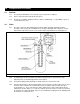
1.2 Warning Tags and Labels The warning tag illustrated below in Figure 1-1 is supplied with each hoist shipped from the factory. If the tag is not attached to your hoist or hoist’s pendant cord, order a tag from your dealer and install it. Read and obey all warnings attached to this hoist. Tag is not shown actual size.
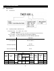
2.0 Technical Information 2.1 Specifications 2.1.1 Product Code 2.1.
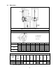
2.2 Dimensions Figure 2-2 Hoist Dimensions (See Table 2-3) Table 2-2 Hook Dimension* C = Chain Hook B = Body Hook Units = inch Capacity Code Hook 005L 010L 020L a b c d e g C 1.1 0.7 0.9 0.7 1.4 0.9 B 1.0 0.6 0.9 0.6 1.7 1.1 C 1.4 0.9 1.2 0.9 1.7 1.2 B 1.2 0.8 1.0 0.8 1.9 1.3 C 1.9 1.1 1.6 1.1 2.0 1.5 B 1.6 1.0 1.3 1.0 2.1 1.6 *Refer to Section 5.7 for inspection dimensions and limits.
3.0 Preoperational Procedures 3.1 Gearbox 3.2 3.1.1 The gearbox is filled with the correct amount of grease at the time of shipment. 3.1.2 Refer to Section 6.3 when replacing the gear grease. 3.1.3 Gear grease for TNER is Sumiplex L-Mo No.1 (Part No. SA1BS1855). 1 oz (30 milliliter) of grease is used to lubricate the gears. Chain 3.2.1 The chain components include Ball Stopper, Chain Coupling, Chain Clip and Chain Container Assembly.
3.2.5 3.2.6 Operating this hoist without the correct Harrington chain container may create a potentially harzardous situation. To avoid this potentially hazardous situation, always operate this hoist with the correct chain container installed. Each chain container indicates the maximum length of the load chain that can be stored in the container. The amount of chain the container must hold is equal to the lift on the hoist.
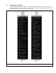
3.2.7 Verify that the load chain is not twisted or tangled prior to operating the hoist. Make sure the chain hook on 2 Ton double fall models is not capsized. See Figures 3-3 and 3-4. Correct all chain irregularities before conducting the first hoist operation. Figure 3-3 Twist in Load Chain – 2 Ton Double Fall Models Figure 3-4 Capsized Hook and Chain –Double Fall Models 3.3 Mounting Location 3.3.1 3.3.
3.4 Mounting the Hoist 3.4.1 Hook Mounted to a Fixed Location - Attach the hoist’s hook to the fixed suspension point. 3.4.2 The hoist may be mounted by the chain hook or the body hook to a fixed suspension point. 3.4.3 3.5 Ensure that the fixed suspension point rests on the center of the hook’s saddle and that the hook’s latch is engaged. Electrical Connections 3.5.1 3.5.2 Supplying this hoist with the incorrect power source can lead to serious damage and/or injury.
Figure 3-6 Cable Support Assembly 3.5.8 Connection to Electrical Power Source - The red, blue and black wires of the Power Supply Cable should be connected to an Electric Power Disconnect Switch or Circuit Breaker. This connection should be made so that the hoist is phased properly. Refer to Section 3.6.10 for instructions on how to check for correct power supply phase connection. 3.5.
3.6 Preoperational Checks and Trial Operation 3.6.1 Confirm the adequacy of the rated capacity for all slings, chains, wire ropes and all other lifting attachments before use. Inspect all load suspension members for damage prior to use and replace or repair all damaged parts. 3.6.2 Verify and correct all chain irregularities prior to operating the hoist. Refer to Section 3.2. 3.6.3 Measure and record the “k” dimension of all hooks on hoist.
4.0 Operation 4.1 Introduction DO NOT WALK UNDER A SUSPENDED LOAD HOIST OPERATORS SHALL BE REQUIRED TO READ THE OPERATION SECTION OF THIS MANUAL, THE WARNINGS CONTAINED IN THIS MANUAL, INSTRUCTION AND WARNING LABELS ON THE HOIST OR LIFTING SYSTEM, AND THE OPERATION SECTIONS OF ANSI/ASME B30.16 and ANSI/ASME B30.10. THE OPERATOR SHALL ALSO BE REQUIRED TO BE FAMILIAR WITH THE HOIST AND HOIST CONTROLS BEFORE BEING AUTHORIZED TO OPERATE THE HOIST OR LIFTING SYSTEM.
The operation of an overhead hoist involves more than activating the hoist’s controls. Per the ANSI/ASME B30 standards, the use of an overhead hoist is subject to certain hazards that cannot be mitigated by engineered features, but only by the exercise of intelligence, care, common sense, and experience in anticipating the effects and results of activating the hoist’s controls.
Improper operation of a hoist can create a potentially hazardous situation which, if not avoided, could result in minor or moderate injury, or property damage. To avoid such a potentially hazardous situation THE OPERATOR SHALL: • Maintain a firm footing or be otherwise secured when operating the hoist. • Use the hoist manufacturer’s recommended parts when repairing the unit. • Check brake function by tensioning the hoist prior to each lift operation.
5.0 Inspection 5.1 General 5.1.1 5.2 The inspection procedure herein is based on ANSI/ASME B30.16. The following definitions are from ANSI/ASME B30.16 and pertain to the inspection procedure below. Designated Person – a person selected or assigned as being competent to perform the specific duties to which he/she is assigned.
5.3 Frequent Inspection 5.3.1 Inspections should be made on a FREQUENT basis in accordance with Table 5-1, “Frequent Inspection.” Included in these FREQUENT Inspections are observations made during operation for any defects or damage that might appear between Periodic Inspections. Evaluation and resolution of the results of FREQUENT Inspections shall be made by a designated person such that the hoist is maintained in safe working condition.
5.5 Occasionally Used Hoists 5.5.1 5.6 5.7 Hoists that are used infrequently shall be inspected as follows prior to placing in service: Hoist Idle More Than 1 Month, Less Than 1 Year: Inspect per FREQUENT Inspection criteria in Section 5.3. Hoist Idle More Than 1 Year: Inspect per PERIODIC Inspection criteria in Section 5.4. Inspection Records 5.6.
Table 5-3 Hoist Inspection Methods and Criteria Item Method Criteria Action Hooks - Yoke Assembly Visual Should be free of significant rust, weld splatter, nicks, gouges. Holes should not be elongated, fasteners should not be loose, and there should be no gap between mating parts. Tighten or replace as required. Hooks - Swivel Bearing Visual, Function Bearing parts and surfaces should not show significant wear, and should be free of dirt, grime and deformations.
Table 5-3 Hoist Inspection Methods and Criteria Item Method Criteria Action Bolts, Nuts and Rivets Visual, Check with Proper Tool Bolts, nuts and rivets should not be loose. Tighten or replace as required. Motor Brake Measure, Visual Motor brake gap should be adjusted to the distance shown in Table 6-1 before measuring the brake wear. Brake lining dimension “A” should not be less than discard value listed in Table 5-6. Refer to Section 6.
Table 5-4 Chain Hook & Bottom Hook Dimensions “k” Measured When New: Chain: ________________________ Body: ________________________ C = Chain Hook B = Body Hook "u" Dimension inch (mm) "t" Dimension inch (mm) Nominal "k" Dimension* inch (mm) Standard Discard Standard Discard C 1.65 (42) 0.93 (23.5) 0.83 (21) 0.69 (17.5) 0.63 (16) B 1.92 (48.8) 0.86 (21.8) 0.77 (19.6) 0.63 (16.0) 0.57 (14.4) C 1.97 (50) 1.22 (31) 1.10 (28) 0.89 (22.5) 0.79 (20) B 2.22 (56.3) 1.04 (26.5) 0.94 (23.
Table 5-6 Motor Brake Wear Dimensions Brake must be properly adjusted before measuring "A". See Section 6.3 "A" Dimension - inch (mm) Capacity Code Standard Discard 005L 0.67 (17) 0.61 (15.5) 010L, 020L 0.85 (21.5) 0.
6.0 Maintenance and Handling 6.1 Lubrication 6.1.1 Load Chain For longer life, the load chain should be lubricated. The load chain lubrication should be accomplished after cleaning the load chain with an acid free cleaning solution. Apply Harrington lubricating grease (Part No. ER1BS1951) or an equivalent to industrial general lithium grease, NLGI No. 0, to the bearing surfaces of the load chain links as indicated by the shaded areas in Figure 6-1.
6.1.3 Gear Box: Using an incorrect type/grade of gearbox grease or the wrong quantity of grease may prevent the friction clutch from working properly and may affect the ability of the hoist to hold the load. Refer to Section 3.1 for the correct grease and quantity. If experiencing abnormal noise or unusual gearbox operation, have the gearbox serviced by a qualified individual. Always replace the gearbox grease when servicing the gearbox. 6.
6.2.3 Brake Gap (G) - The Brake Gap should be measured between the Brake Drum and Pull Rotor. Adjustment of the Brake Gap is accomplished by turning the Adjustment Nut in the center of the Motor Cover as shown in the figure with Table 6-1. Do this as follows: 5) Bend the tab of the Lock Washer away from the Adjusting Nut so that the Adjusting Nut can be rotated. 6) Using a spanner wrench and a feeler gauge, rotate the Adjusting Nut to attain the proper Brake Gap per Table 6-1.
Table 6-1 Motor Brake Gap Brake Gap (G) inch (mm) 6.2.4 0.020 (0.5) Brake Lining Inspection –The brake lining is designed for a long life and should provide years of trouble-free service. If the brake lining is being inspected due to excessive load chain drift during operation (see Section 5.7), disassemble the motor brake and inspect all motor brake parts. Braking surfaces should be clean, free of grease/oil and should not be glazed. Replace the Brake Drum and/or Motor Cover if necessary.
both its end links have the same orientation. If the load chain is being replaced due to damage or wear out, destroy the old chain to prevent its reuse. 1) When replacing load chain, check for wear on mating parts, i.e. Load Sheave, Chain Guides and Idle Sheaves, and replace parts if necessary. 2) Remove all chain components including the Chain Hook Set Assembly, Ball Stoppers, Chain Pin, Chain Coupling and Chain Clip from the chain for reuse on new chain.
6.4 Friction Clutch 6.4.1 6.5 Storage 6.5.1 6.6 Friction Clutch – If abnormal operation or slippage occurs do NOT attempt to disassemble or adjust the Friction Clutch. Replace the worn or malfunctioning Friction Clutch as an assembly with a new, factory adjusted part. The storage location should be clean and dry. Outdoor Installation 6.6.1 For hoist installations that are outdoors, the hoist should be covered when not in use. 6.6.
7.0 Troubleshooting HAZARDOUS VOLTAGES ARE PRESENT IN THE HOIST AND IN CONNECTIONS BETWEEN COMPONENTS. Before performing ANY troubleshooting on the equipment, de-energize the supply of electricity to the equipment, and lock and tag the supply device in the de-energized position. Refer to ANSI Z244.1, “Personnel Protection Lockout/Tagout of Energy Sources.” Only Trained and competent personnel should inspect and repair this equipment.
Table 7-1 Troubleshooting Guide Symptom Hoist lifts but will not lower Hoist lowers but will not lift Hoist will not lift rated load or does not have the proper lifting speed Load drifts excessively when hoist is stopped Cause Remedy Down circuit open Check circuit for loose connections. Check down side of limit switch for malfunction. Broken conductor in pendant cord Check the continuity for each conductor in the cable. If one is broken, replace entire cable.
Table 7-1 Troubleshooting Guide Symptom Motor or brake overheating Hoist operates intermittently Cause Remedy Excessive load Reduce load to within rated capacity of hoist. Excessive duty cycle Reduce frequency of lifts. Wrong voltage or frequency Check voltage and frequency of power supply against the rating on the nameplate on the motor. Brake drags Check brake adjustment for proper clearance.
8.0 Warranty Warranty explanation and terms. All products sold by Harrington Hoists, Inc.
This Page Intentionally Left Blank 36
9.0 Parts List When ordering Parts, please provide the Hoist code number, lot number and serial number located on the Hoist nameplate (see fig. below). Reminder: Per sections 1.1 and 3.6.4 to aid in ordering Parts and Product Support, record the Hoist code number, lot number and serial number in the space provided on the cover of this manual. ER/NER Series Nameplate 37 The parts list is arranged into the following sections: Section 9.1 Housing and Motor Parts……………………………………………….…………………………….. 38 9.
9.
Figure Part Name No.
24 Part Name Motor Frame with Stator 208-230/460V-3-60 Parts Per Hoist 005L 1 SA1DHM05L5A1 SA1DHM010L5A1 4 90912138 9091275 010L 020L 40 25 Socket Bolt 26 Set Pin S 2 ES120003 ES120010S 27 Packing M 1 ER1BS9118 ER1CS9118 28 Body B 1 SA1BL9101 SA1CL9101 30 Oil Plug 2 E3S111003 31 Plug Packing 2 E3S112003 32 Set Pin S 2 33 Packing G 1 ER1BS9116 35 Gear Case F 1 SA1BL9103 36 Socket Bolt 4 9091259 37 Toothed Lock Washer 4 9679709 38 Name Plate SP 1 39
This Page Intentionally Left Blank
9.
Part Name Parts Per Hoist 005L 010L 020L 43 1 Bearing Holder 1 ER1CS9110 2 Socket Bolt 3 90912133 3 Snap Ring 1 9047262 4 Collar B 1 ER1BS9111 5 Pinion Assembly 1 ER1BS5220 SA1CL5220 6 Oil Seal 1 ES221003 ES221010S 7 Ball Bearing 1 9000907 9000909 8 Load Sheave 1 ER1BL9241 ER1CL9241 9 Oil Seal 1 ES232005S ES232005S 10 Ball Bearing 1 11 Snap Ring 1 9047262 9047262 12 Load Gear 1 ER1BL9240 ER1CS9240 13 Snap Ring 1 9047130 9047135 14 Ball Bearin
9.
Figure No.
9.
Fig No Part Name Parts Per Hoist 005L SA1BL9331 010L 020L 1 Chain Guide A 1 3 Guide Roller 1 4 Roller Pin 1 5 Limit Lever S 1 SA1BL9337 SA1CL9337 24 Chain Guide B 1 ER1BL9332 ER1CL9332 11 Mach.
9.
Fig No Part Name Parts Per Hoist 005L 010L 1 Limit Switch Assembly 1 ER1BS1551 2 Socket Bolt 3 9091247 3 Spring Washer 3 4 Plate Assembly 1 9012709 SA1DHM05L5A2 SA1DHM10L5A2 5 Transformer 3 TRF62M611 6 Machine Screw 2 MS555010 7 Terminal Plate 1 ECP1309AD 8 Mach. Screw w/ Spring Washer 2 J1AW24001010 9 E-Stop Contactor 1 MGC14306C 10 Mach.
9.6 Power Supply and Pendant Parts 50 10.
Fig No 1 Part Name Parts Per Hoist 005L 010L Socket Holder Assembly 1 SA1CL1511 2 Socket Holder 1 SA1CL9511 3 Holder B 2 ECP5924AB 4 Holder Packing 2 ECP5924AC 5 Holder Nut 2 ECP5924AD 6 Machine Screw w/ Spring Washer 2 J1AP26001212 7 Socket Holder Packing 1 ER1BS9512 8 Machine Screw w/ Spring Washer 4 MS561010 9 Cable Support Arm 1 SA1BS9541 10 Cable Support 1 E4YS0059822 11 Cable Support Pin B 1 E3ES0029541 12 Split Pin 1 9009402 13 Power Supply Cable 4
This Page Intentionally Left Blank 52
Appendix A: Wiring Diagram 53
Appendix B: CE Declaration of Conformity EC DECLARATION OF CONFORMITY We, Harrington Hoists, Inc., 401 West End Ave., Manheim, PA 17545, USA declare under our sole responsibility that the products: Electric chain hoist TNER for use with or without the relevant serial trolleys in capacity range of 1/2 ton up to 2 ton, to which this declaration relates is in conformity with the following EC directives and standards.
This Page Intentionally Left Blank 55
www.harringtonhoists.com Harrington Hoists, Inc. 401 West End Avenue Manheim, PA 17545-1703 Phone: 717-665-2000 Toll Free: 800-233-3010 Fax: 717-665-2861 Harrington Hoists – Western Division 2341 Pomona Rd.