EFFECTIVE: May 1, EFFECTIVE: October 13,2006 2010 CHEETAH AIR POWERED CHAIN HOIST TCS SERIES ¼ Ton, ½ Ton and 1 Ton Capacity Code, Lot and Serial Number This equipment should not be installed, operated or maintained by any person who has not read and understood all the contents of this manual. Failure to read and comply with the contents of this manual can result in serious bodily injury or death, and/or property damage.
Table of Contents Section 1.0 2.0 3.0 4.0 Page Number Important Information and Warnings…………………………………………………………………4 1.1 Terms and Summary 1.2 Warning Tags and Labels Technical Information………………………………………………………………………………… 8 2.1 Specifications 2.2 Dimensions 2.3 Part Names Pre-operational Procedures………………………………………………………………………....13 3.1 Air Supply System Requirements 3.2 Air Supply Capacity And Regulation 3.3 Lubrication 3.4 Filtration 3.5 Air Dryer 3.6 Piping, Hoses And Fittings 3.
Section 5.0 6.0 7.0 Page Number Inspection………………………………………………………………………….………………… 27 5.1 General 5.2 Inspection Classification 5.3 Frequent Inspection 5.4 Periodic Inspection 5.5 Occasionally Used Hoists 5.6 Inspection Records 5.7 Inspection Methods and Criteria Lubrication…………………………………………………………………………………………... 34 6.1 Air Hoist Lubrication 6.2 Load Chain Lubrication 6.3 Hooks and Suspension Components Maintenance & Handling…………………………………………………………………………… 36 7.1 Brake 7.2 Load Chain 7.
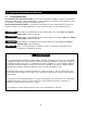
1.0 Important Information and Warnings 1.1 Terms and Summary This manual provides important information for personnel involved with the installation, operation and maintenance of this product. Although you may be familiar with this or similar equipment, it is strongly recommended that you read this manual before installing, operating or maintaining the product. Danger, Warning, Caution and Notice - Throughout this manual there are steps and procedures that can present hazardous situations.
Equipment described herein is not designed for and MUST NOT be used for lifting, supporting, or transporting people, or for lifting or supporting loads over people. Equipment described herein should not be used in conjunction with other equipment unless necessary and/or required safety devices applicable to the system, crane, or application are installed by the system designer, system manufacturer, crane manufacturer, installer, or user.
HAZARDOUS AIR PRESSURE IS PRESENT IN THE HOIST, IN THE SUPPLY OF COMPRESSED AIR TO THE HOIST, AND IN THE CONNECTIONS BETWEEN COMPONENTS. Before performing ANY maintenance on the equipment, de-energize the supply of compressed air to the equipment, and lock and tag the supply device in the de-energized position. Refer to ANSI Z244.1, “Personnel Protection - Lockout/Tagout of Energy Sources.” Only trained and competent personnel should inspect and repair this equipment.
1.2 Warning Tags and Labels The warning tag illustrated below in Figure 1-1 is supplied with each hoist shipped from the factory. If the tag is not attached to your hoist (for pendant control, the warning tag is attached to the pendant hose; for the pull cord control, the warning tag is attached to the up cord), order a tag from your dealer and install it. See parts list in the parts section of this manual. Read and obey all warnings attached to this hoist. Tag is not shown actual size.
2.0 2.1 Technical Information Specifications 2.1.1 Product Code 2.1.2 Operating Conditions and Environment Temperature range: Relative Humidity: Noise Level: Supply Air: Air Consumption: Air Lubrication Requirements: Air Filtration Requirements: +14° to +140°F (-10° to +60°C) 85% or less 83 dba maximum @ 1 meter when lifting rated load 93 dba maximum @ 1 meter when lowering rated load 60 to 90 psi (0.4 to 0.6 MPa) 60 to 75 cfm (1.7 to 2.
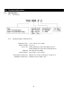
Cord Model Pendant Model Table 2-1 Hoist Specifications Cap. (Tons) Product Code 1/4 TCS250P 1/2 TCS500P 1 Load Chain Up/Down Push Up/Down Speeds Air Consumption Rates Diameter Standard Button Net (mm) (ft/min @ 90 psi) Lift Hose Weight (cubic ft/min @ 90 psi) x (ft) L (lbs) Chain Fall No Load w/Full Load No Load w/Full Load (ft) Lines Weight for Additional One foot of Lift (lbs) 8.1 207/125 121/197 78/67 64/74 6.3 X 1 42 0.6 8.1 108/62 60/108 74/64 60/71 6.3 X 1 42 0.
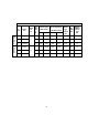
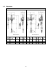
2.2 Dimensions Table 2-2 TCS with Pendant Control Dimensions Double Fall Hoist Single Fall Hoist Cap. (Tons) Product Code Headroom C (in) a (in) b (in) d (in) e (in) g (in) h (in) i (in) j (in) 1/4 TCS250P 16.3 14.4 6.6 6.3 7.6 1.0 4.4 2.2 1.0 1/2 TCS500P 16.3 14.4 6.6 6.3 7.6 1.0 4.4 2.2 1.0 1 TCS1000P2 17.9 14.4 9.0 6.3 8.0 1.1 6.3 2.8 1.
Table 2-3 TCS with Cord Control Dimensions Single Fall Hoist Double Fall Hoist Cap. (Tons) Product Code Headroom C (in) a (in) b (in) d (in) e (in) g (in) h in) i (in) j (in) 1/4 TCS250C 16.3 14.4 8.7 6.3 7.6 1.0 5.3 3.3 1.0 1/2 TCS500C 16.3 14.4 8.7 6.3 7.6 1.0 5.3 3.3 1.0 1 TCS1000C2 17.9 14.4 9.0 6.3 8.0 1.1 6.3 2.8 1.9 Table 2-4 Top and Bottom Hook Dimension* Units = inch Product Code TCS250C/P TCS500C/P TCS1000C2/P2 a b c d e f g h 0.6 0.6 1.
2.
3.0 Preoperational Procedures 3.1 Air Supply System Requirements 3.1.1 3.1.2 3.1.3 3.2 Pressure and Flow - Verify that the air supply system has capacity to supply your air hoist with required pressure and flow. Otherwise the hoist may operate poorly or may fail to operate. See Section 3.2. Lubrication - The hoist requires lubrication for proper operation. The oil in the air supply is the primary source of lubrication to the hoist.
3.4.1 3.4.2 The air entering the hoist inlet must not contain any particulate greater than 5 microns in size. Therefore, the hoist must have a 5 micron filter in its air supply. The filter must be upstream of the lubricator. The filter servicing the hoist can also service other hoists and air consuming equipment. In this case, the air filter must be in sized for the total air consumption of the equipment it is servicing. Air Dryer - 3.
Figure 3-2 Typical Air Supply Filter, Regulator, and Lubricator. 3.6.2 Piping - Pipe should be sized to accommodate the hoist airflow requirements. Table 3-1 gives recommended pipe sizes. Table 3-1 Air Supply Pipe and Hose Sizes 3.6.
3.6.5 3.7 Mounting Location 3.7.1 3.7.2 3.8 Before connecting the hoist to its air supply line; perform the proper draining and purging procedures to prevent contaminants or moisture from entering the hoist. Prior to mounting the hoist ensure that the suspension and it supporting structure are adequate to support the hoist and its loads. If necessary consult a professional that is qualified to evaluate the adequacy of the suspension location and its supporting structure.
3.9.3 3.10 Ensure that the fixed suspension point rests on the center of the hook’s saddle and that the hook’s latch is engaged. Optional Chain Container 3.10.1 Follow instructions below to install the optional chain container. Refer to Figure 3-5. 1) Attach the metal bracket on top of the chain container to the lower boss on the side of the hoist body using the M8 Socket Bolt, Washers, Nut and Split Pin provided.
3) Inject a small quantity (approximately 20 drops) of turbine oil (see Section 6.0) into the hoist’s inlet port 4) Plug the inlet port 3.12 Preoperational Checks and Trial Operation 3.12.1 3.12.2 Check for the availability of required operating air pressure of between 60 psi to 90 psi at the hoist's inlet port before trying to operate the hoist. Verify that the load chain is not twisted or tangled and that the bottom hook is not capsized prior to operating the hoist.
3.12.3 3.12.4 Confirm the adequacy of the rated capacity for all slings, chains, wire ropes and all other lifting attachments before use. Inspect all load suspension members for damage prior to use and replace or repair all damaged parts. Verify that the Chain/Limit Lever is operational and can move freely in both the up and down directions. For reference see Figure 3-8. Figure 3-8 Limit Switch Components – TCS250C/P, TCS500C/P and TCS1000C2/P2 3.12.
3.12.13 Confirm proper operation. Before operating read and become familiar with Section 4 - Operation. Before operating ensure that the hoist (and trolley) meets the Inspection, Testing and Maintenance requirements of ANSI/ASME B30.16. Before operating ensure that nothing will interfere with the full range of the hoist’s (and trolley’s) operation. 3.12.4 Proceed with trial operation to confirm proper operation. Make sure hook travel is in the same direction as shown on controls.
4.0 Operation 4.1 Introduction DO NOT WALK UNDER A SUSPENDED LOAD HOIST OPERATORS SHALL BE REQUIRED TO READ THE OPERATION SECTION OF THIS MANUAL, THE WARNINGS CONTAINED IN THIS MANUAL, INSTRUCTION AND WARNING LABELS ON THE HOIST OR LIFTING SYSTEM, AND THE OPERATION SECTIONS OF ANSI/ASME B30.16 and ANSI/ASME B30.10. THE OPERATOR SHALL ALSO BE REQUIRED TO BE FAMILIAR WITH THE HOIST AND HOIST CONTROLS BEFORE BEING AUTHORIZED TO OPERATE THE HOIST OR LIFTING SYSTEM.
The operation of an overhead hoist involves more than activating the hoist’s controls. Per the ANSI/ASME B30 standards, the use of an overhead hoist is subject to certain hazards that cannot be mitigated by engineered features, but only by the exercise of intelligence, care, common sense, and experience in anticipating the effects and results of activating the hoist’s controls.
Improper operation of a hoist can create a potentially hazardous situation which, if not avoided, could result in minor or moderate injury, or property damage. To avoid such a potentially hazardous situation THE OPERATOR SHALL: • Maintain a firm footing or be otherwise secured when operating the hoist. • Use the hoist manufacturer’s recommended parts when repairing the unit. • Check brake function by tensioning the hoist prior to each lift operation.
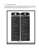
4.3.3 Cord Control - When using a hoist with cord control, pull down on the appropriate colored cord to raise or lower the hoist. White indicates the raise control and red indicates lowering control. Release the cords to stop the hoist. Refer to Figure 4-2 below. Figure 4-2 Cord Control 4.3.4 4.4 Make sure the motor completely stops before reversing direction. Adjusting the Controls 4.4.1 For pendant control, the speed can be adjusted by the amount the lever is depressed.
4.5 Speed Adjustment Controls 4.5.1 4.5.2 The hoist is equipped with speed adjustment controls. The controls allow the hoist lifting and lowering speeds to be reduced for those applications requiring slower speeds or better speed control. The speed adjustment controls are set for the highest speed from the factory. The speed adjustment controls are located on top of the valve section of the hoist as shown in Figure 4-4. The hoist must be stopped when adjusting the lifting and lowering speeds.
4.6 Pendant Controllability Adjustment 4.6.1 The standard pendant hose length is 8.1 feet. For longer pendant hose lengths the speed controllability from the pendant may be diminished. The reduction in speed control is a result of pressure loss due to the longer pendant hose. The pendant hose extension adjustment control provides a screw adjustment method to reduce the air pressure loss to provide normal pendant/hoist operation.
5.0 Inspection 5.1 General 5.1.1 5.2 The inspection procedure herein is based on ANSI/ASME B30.16. The following definitions are from ANSI/ASME B30.16 and pertain to the inspection procedure below. Designated Person - a person selected or assigned as being competent to perform the specific duties to which he/she is assigned.
5.3 Frequent Inspection 5.3.1 Inspections should be made on a FREQUENT basis in accordance with Table 5-1, “Frequent Inspection.” Included in these FREQUENT Inspections are observations made during operation for any defects or damage that might appear between Periodic Inspections. Evaluation and resolution of the results of FREQUENT Inspections shall be made by a designated person such that the hoist is maintained in safe working condition.
5.5 Occasionally Used Hoists 5.5.1 5.6 5.7 Hoists that are used infrequently shall be inspected as follows prior to placing in service: Hoist Idle More Than 1 Month, Less Than 1 Year: Inspect per FREQUENT Inspection criteria of Section 5.3 above. Hoist Idle More Than 1 Year: Inspect per PERIODIC Inspection criteria of Section 5.4 above. Inspection Records 5.6.
Table 5-3 Hoist Inspection Methods and Criteria (continued) Item Method Criteria Action Hooks - Bent Shank or Neck Visual Shank and neck portions of hook should be free of deformations Replace. Hooks - Yoke Assembly Visual Should be free of significant rust, weld splatter, nicks, gouges. Holes should not be elongated, fasteners should not be loose, and there should be no gap between mating parts. Clean/Lubricate, or replace as required.
Table 5-3 Hoist Inspection Methods and Criteria (continued) Item Method Criteria Action Housing and Mechanical Components Visual, Auditory, Vibration, Function Hoist components including load blocks, suspension housing, chain attachments, clevises, yokes, suspension bolts, shafts, gears, bearings, pins and rollers should be free of cracks, distortion, significant wear and corrosion. Evidence of same can be detected visually or via detection of unusual sounds or vibration during operation.
Table 5-4 Brake Disc Dimension Hoists Parts View Figure No. Std Dimension Inch (mm) Minimum Value for Replacement Inch (mm) TCS250C2/P2 TCS500C2/P2 TCS1000C2/P2 152 T = 0.31 (8) T = 0.29 (7.3) Table 5-5 Chain Separator Dimensions Hoists Parts View Figure No. Std Dimension Inch (mm) Maximum Value for Replacement Inch (mm) TCS250C2/P2 TCS500C2/P2 TCS1000C2/P2 104 L = 0.51 (13) W = 0.95 (24) L = 0.63 (16) W = 1.04 (26.
Table 5-6 Top Hook & Bottom Hook Dimensions Dimensions K and U should be measured and recorded below prior to any use when the hook is first placed into service. Hoists Parts View Figure No.
6.0 Lubrication 6.1 Air Hoist Lubrication 6.1.1 6.1.2 6.1.3 6.2 See Section 3.0 for lubrication requirements. Lubrication to the motor will be provided primarily by the air supply lubricator. The recommended amount is 10-15 drops/minute (2-3cc/min.). Refer to Table 6-1 below for the approved lubricant for use with your air hoist. Additional lubrication to the reduction gears is not necessary.
6.3 Hooks and Suspension Components 6.3.1 Hooks - Bearings should be cleaned and lubricated at least once per year for normal usage. Clean and lubricate more frequently for heavier usage or severe conditions. 6.3.2 Suspension Pins - Lubricate at least twice per year for normal usage; more frequently for heavier usage or severe conditions.
7.0 Maintenance and Handling 7.1 Brake 7.1.1 The hoist brake is not adjustable. 7.1.2 Inspect the brake disc in accordance with Section 5.7, Table 5-4. 7.1.3 The following is the hoist brake inspection procedure. Refer to Figure 7-1. 1) HAZARDOUS AIR PRESSURE IS PRESENT IN THE HOIST, IN THE SUPPLY OF COMPRESSED AIR TO THE HOIST, AND IN THE CONNECTIONS BETWEEN COMPONENTS. Shut off the air supply and stop the airflow completely. Lock out and tag out in accordance with ANSI Z244.
7.2 Load Chain 7.2.1 7.2.2 Lubrication and Cleaning – Refer to Section 6.2. Replacement 1) 7) An air supply line must be connected to the hoist in order to perform the following procedures. Be certain that the replacement chain is obtained from Harrington and is the exact size, grade and construction as the original chain. The new load chain must have an even number of links so that the end links are oriented 90° from each other.
Figure 7-2 Load Chain Installation Diagram Figure 7-3 Single Fall Chain Connections 38
Figure 7-4 Double Fall Chain Connections 7.3 Pendant 7.3.1 The following procedure covers the installation of the Pendant Hose (Parts List Figure Number 360) and the Pendant Valve. Refer to Figure 7-5. 1) Place boot on the ends of the Pendant Hoses to be attached to the Manifold Block on the hoist. 2) Attach pendant hose to hoist body using the one-piece fittings and screw type clamps (hose bands).
Figure 7-5 Pendant Hose Connections 7.4 Load Sheave Inspection 7.4.1 1) Perform this inspection by removing the chain separator and viewing the load sheave while operating the hoist slowly, with no load, and in accordance with Section 4 “Operation”. Refer to Figure 7-6 and remove the chain separator as follows: An air supply line must be connected to the hoist in order to perform the following procedures.
Figure 7-6 Load Sheave Inspection 7.5 7.6 Storage 7.5.1 Whenever the hoist is to be placed into storage, place extra lubricating oil into the air inlet opening and circulate the air motor before plugging the inlet. Make certain that no debris, dirt or moisture is allowed to enter the air hoist through air inlet opening during preparations for storage. 7.5.2 The storage location should be clean and dry. Outdoor Installation 7.6.
8.0 Troubleshooting HAZARDOUS AIR PRESSURE IS PRESENT IN THE HOIST, IN THE SUPPLY OF COMPRESSED AIR TO THE HOIST, AND IN CONNECTIONS BETWEEN COMPONENTS. Before performing ANY maintenance on the equipment, de-energize the supply of compressed air to the equipment, and lock and tag the supply device in the de-energized position. Refer to ANSI Z244.1, “Personnel Protection - Lockout/Tagout of Energy Sources.” Only Trained and competent personnel should inspect and repair this equipment.
Table 8-1 Troubleshooting Guide (continued) Symptom Hoist moving in wrong direction (pendant control) Hoist lowers but will not lift Hoist continues running after pendant or cord is released Hoist drifts excessively when hoist is stopped Cause Remedy Pendant control hoses are terminated to incorrect ports on hoist body. Hoist is overloaded. Faulty pendant control or control hose(s) Lack of air pressure or partial loss of or leakage in air supply. Connect the control tubes in accordance with Section 7.
9.0 Warranty Warranty explanation and terms. All products sold by Harrington Hoists, Inc.
10.0 Parts Information A complete parts list is available from Harrington Hoists and is supplied separately with your hoist. The parts list is also available from Harrington's web site (www.harringtonhoists.com) or from any Harrington facility (see back cover of this manual). When ordering Parts, please provide the Hoist code number located on the Hoist nameplate (see fig. below). Reminder: Per Sections 3.11.6 and 1.
10.
Motor, Valve Body and Controls Figure Number 1 2 3 4 5 6 7 8 9 10 11 12 13 14 15 16 17 18 19 20 21 22 23 24 25 26 27 28 29 30 31 32 50 51 52 53 54 55 56 57 58 59 60 61 62 63 64 65 66 67 68 69 70 71 72 73 75 76 77 Parts per hoist Throttle Valve 2 Valve Bushing (Up) 1 Valve Bushing (Down) 1 Spring Seat 2 Valve Cap 2 Valve Body 1 Bush Cap 2 Piston 2 Exhaust Plate 1 Silencer (S) 4 Adjust Cap 2 Inlet Bushing 1 Screen 1 Valve Spring 2 Spring 2 Valve Gasket 1 Bushing 2 Socket Bolt 4 Button-Head Screw 2 Set Screw
10.
Brake, Gears and Load Suspension Components Figure Number Name Parts per hoist Part Number Figure Number Name Parts per hoist Part Number 100 Center Housing 1 TCS426230A00 212 Bearing 2 TCS130113001 101 Load Sheave 1 TCS426230A50 213 Bearing 1 TCS130120004 102 Coupling 1 TCS426230200 214 Bearing 1 9000105 103 Chain Guide 1 TCS426230350 215 Needle Bearing 3 TCS130131020 104 Chain Separator 1 TCS426230360 216 Needle Bearing 3 TCS130131212 105 Bearing 2 90005
Brake, Gears and Load Suspension Components TCS 1000 Top Hook Assembly 282 Top Hook Set 1 282A Top Hook Assembly 70003 1 70004 283 Hook Latch 1 TCR426221S30 284 Hook Spring 1 TCR130802258 285 Socket Bolt 1 9091232 286 U Nut 1 E2D853125 287 Hook End Piece 1 TCS426251570 288 Socket Bolt 2 TCS131706020 289 Hook Joint Bolt 1 TCR426244580 290 Washer 1 9012511 291 U Nut 1 9098504 TCS 1000 Lower Hook Assembly 292 Bottom Hook Set 1 70005 292A Bottom Hook Assembly 1 70
Figure 10-2 Chain Container Assembly (optional) Figure Number 400 Name Parts per hoist Part Number Chain Container Assembly 1 TCSS2623055C 401 Socket Bolt 1 9091280 402 Flat Washer 2 9012513 403 Hex Nut 1 9093424 404 Split Pin 1 90094165 405 Socket Bolt 1 9091252 406 Flat Washer 2 9012511 407 Hex Nut 1 9093420 408 Split Pin 1 9009413 409 Load Chain 8 Links LCCF005 410 Socket Bolt 1 9091251 411 Flat Washer 2 9012511 412 Lock Nut 1 9098504 413 Machine
www.harringtonhoists.com Harrington Hoists, Inc. 401 West End Avenue Manheim, PA 17545-1703 Phone: 717-665-2000 Toll Free: 800-233-3010 Fax: 717-665-2861 Harrington Hoists – Western Division 2341 Pomona Rd.