EFFECTIVE: October 7, 2010 AIR POWERED CHAIN HOIST TCR SERIES ¼ Ton through 6 Ton Capacity Code Number and Serial Number This equipment should not be installed, operated or maintained by any person who has not read and understood all the contents of this manual. Failure to read and comply with the contents of this manual can result in serious bodily injury or death, and/or property damage.
Table of Contents Section 1.0 2.0 3.0 4.0 Page Number Important Information and Warnings…………………………………………………………………4 1.1 Terms and Summary 1.2 Warning Tags and Labels Technical Information…………………………………………………………………………………8 2.1 Specifications 2.2 Dimensions 2.3 Part Names Pre-operational Procedures………………………………………………………………………... 15 3.1 Air Supply System Requirements 3.2 Air Supply Capacity And Regulation 3.3 Lubrication 3.4 Filtration 3.5 Air Dryer 3.6 Piping, Hoses And Fittings 3.
Section 5.0 6.0 7.0 Page Number Inspection……………………………………………………………………………………………. 28 5.1 General 5.2 Inspection Classification 5.3 Frequent Inspection 5.4 Periodic Inspection 5.5 Occasionally Used Hoists 5.6 Inspection Records 5.7 Inspection Methods and Criteria Lubrication…………………………………………………………………………………………... 35 6.1 Air Hoist Lubrication 6.2 Load Chain Lubrication 6.3 Hooks and Suspension Components Maintenance & Handling…………………………………………………………………………… 36 7.1 Load Limiter 7.
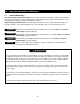
1.0 Important Information and Warnings 1.1 Terms and Summary This manual provides important information for personnel involved with the installation, operation and maintenance of this product. Although you may be familiar with this or similar equipment, it is strongly recommended that you read this manual before installing, operating or maintaining the product. Danger, Warning, Caution and Notice - Throughout this manual there are steps and procedures that can present hazardous situations.
Equipment described herein is not designed for and MUST NOT be used for lifting, supporting, or transporting people, or for lifting or supporting loads over people. Equipment described herein should not be used in conjunction with other equipment unless necessary and/or required safety devices applicable to the system, crane, or application are installed by the system designer, system manufacturer, crane manufacturer, installer, or user.
HAZARDOUS AIR PRESSURE IS PRESENT IN THE HOIST, IN THE SUPPLY OF COMPRESSED AIR TO THE HOIST, AND IN THE CONNECTIONS BETWEEN COMPONENTS. Before performing ANY maintenance on the equipment, de-energize the supply of compressed air to the equipment, and lock and tag the supply device in the de-energized position. Refer to ANSI Z244.1, “Personnel Protection - Lockout/Tagout of Energy Sources.” Only trained and competent personnel should inspect and repair this equipment.
1.2 Warning Tags and Labels The warning tag illustrated below in Figure 1-1 is supplied with each hoist shipped from the factory. If the tag is not attached to your hoist (for pendant control, the warning tag is attached to the pendant hose; for the pull cord control, the warning tag is attached to the up cord), order a tag from your dealer and install it. See parts list in the parts section of this manual. Read and obey all warnings attached to this hoist. Tag is not shown actual size.
2.0 2.1 Technical Information Specifications 2.1.1 Product Code 2.1.
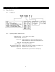
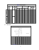
Table 2-1 Hoist Specifications Cord Model Pendant Model Cap. (Tons) 2.2 1/4 1/2 Push Standard Button Lift Hose (ft) L (ft) Product Code TCR250P TCR500P Up/Down Speeds (ft/min @ 90 psi) Up/Down Load Chain Air Consumption Rates Diameter Net (mm) (cubic ft/min @ 90 psi) Weight x (lbs) Chain Fall No Load w/Full Load Lines Weight for Additional One Foot of Lift (lbs) No Load w/Full Load 7.5 7.5 68 / 44 68 / 44 52 / 51 37 / 57 63 / 49 63 / 49 48 / 57 48 / 57 6.3 x 1 6.3 x 1 68 68 0.6 0.6 7.
Table 2-3 TCR with Pendant Control Dimensions Cap. (Tons) Product Code Headroom C (in) a (in) b (in) d (in) e (in) g (in) h (in) i (in) j (in) 1/4 TCR250P 18.2 13.4 6.9 6.1 6.6 1.1 4.9 2.0 1.3 1/2 TCR500P 18.2 13.4 6.9 6.1 6.6 1.1 4.9 2.0 1.3 1 TCR1000P2 20.4 13.4 7.3 6.1 6.6 1.1 5.9 1.5 2.2 1 TCR1000P 18.3 13.4 6.9 6.1 6.6 1.1 4.9 2.0 1.3 2 TCR2000P2 21.8 13.4 7.6 6.1 6.6 1.1 6.0 1.6 2.3 3 TCR3000P 22.2 17.7 8.9 8.0 9.0 1.3 1.9 6.
Table 2-4 TCR with Cord Control Dimensions Cap. (Tons) Product Code Headroom C (in) a (in) b (in) d (in) e (in) g (in) h (in) i (in) j (in) k (in) 1/4 TCR250C 18.2 13.4 6.9 6.1 6.6 1.1 4.9 2.0 1.3 8.3 1/2 TCR500C 18.2 13.4 6.9 6.1 6.6 1.1 4.9 2.0 1.3 8.3 1 TCR1000C2 20.4 13.4 7.3 6.1 6.6 1.1 5.9 1.5 2.2 8.3 1 TCR1000C 18.3 13.4 6.9 6.1 6.6 1.1 4.9 2.0 1.3 8.3 2 TCR2000C2 21.8 13.4 7.6 6.1 6.6 1.1 6.0 1.6 2.3 8.3 3 TCR3000C 22.2 17.
2.
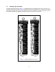
Figure 2-4 Hoist Part Identification Diagrams TCR 1000P2, 1000C2, 2000P2, 2000C2 13
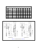
Figure 2-5 Hoist Part Identification Diagrams TCR 3000P, 3000C Figure 2-6 Hoist Part Identification Diagrams TCR 6000P2, 6000C2 14
3.0 Preoperational Procedures 3.1 Air Supply System Requirements 3.1.1 3.1.2 3.1.3 3.2 Pressure and Flow - Verify that the air supply system has capacity to supply your air hoist with required pressure and flow. Otherwise the hoist may operate poorly or may fail to operate. See Section 3.2. Lubrication - The hoist requires lubrication for proper operation. The oil in the air supply is the primary source of lubrication to the hoist.
3.4.2 The filter servicing the hoist can also service other hoists and air consuming equipment. In this case, the air filter must be in sized for the total air consumption of the equipment it is servicing. Air Dryer - 3.5 To prevent corrosion and hoist malfunction, employ an air dryer in the air supply system to ensure that dry air is supplied to the hoist.
3.6.2 Piping - Pipe should be sized to accommodate the hoist airflow requirements. Table 3-1 gives recommended pipe sizes. Table 3-1 Air Supply Pipe and Hose Sizes Diameter of Supply Pipe Diameter of Supply Hose TCR250P, 250C, 500P, 500C, 1000P, 1000C TCR1000P2, 1000C2, 2000P2, 2000C2 Inside diameter 0.75 inch or larger Inside diameter 0.5 inch or larger TCR3000P, 3000C TCR6000P2, 6000C2 Inside diameter 1.0 inch or larger Inside diameter 0.75 inch or larger Model 3.6.
3.6.5 3.7 Mounting Location 3.7.1 3.7.2 3.8 Before connecting the hoist to its air supply line; perform the proper draining and purging procedures to prevent contaminants or moisture from entering the hoist. Prior to mounting the hoist ensure that the suspension and it supporting structure are adequate to support the hoist and its loads. If necessary consult a professional that is qualified to evaluate the adequacy of the suspension location and its supporting structure.
3.9.4 3.10 Ensure that the fixed suspension point rests on the center of the hook’s saddle and that the hook’s latch is engaged . Optional Chain Container 3.10.1 For installation of the optional bag style chain container refer to Figure 3-5 below and perform the following: Make sure all end stoppers and limit locks are installed correctly. See Sections 3.12 and 7.3. Torque all fasteners to the values shown. Feed the chain into the chain container beginning with the free end.
3.12 Preoperational Checks and Trial Operation 3.12.1 3.12.2 Check for the availability of required operating air pressure of between 60 PSI to 90 PSI at the hoist's inlet port before trying to operate the hoist. Verify that the load chain is not twisted or tangled and that the bottom hook is not capsized prior to operating the hoist. Correct all chain irregularities before conducting the first hoist operation. See Figures 3-6 and 3-7.
3.12.4 For Models TCR-250P&C, 500P&C, 1000P2&C2, 1000P&C and 2000P2&C2 verify the limit locks are properly installed on the load chain. For reference see Figure 3-8 for hoist versions 1, A, B and C and Section 7.3.2. For Models TCR-3000P&C and 6000P2&C2 verify that the chain/limit lever is operational and can move freely in both the up and down directions. For reference see Figure 3-9. Versions 1, A and B Version C Only Figure 3-8 Limit Switch Components Figure 3-9 Limit Switch Components 3.12.
3.12.7 Ensure that the hoist is properly installed to either a fixed point, or trolley, whichever applies. 3.12.8 If hoist is installed on a trolley, ensure that trolley is properly installed on the beam, and stops for the trolley are correctly positioned and securely installed on the beam. 3.12.9 Ensure that all nuts, bolts and split (cotter) pins are sufficiently fastened. 3.12.
4.0 Operation 4.1 Introduction DO NOT WALK UNDER A SUSPENDED LOAD HOIST OPERATORS SHALL BE REQUIRED TO READ THE OPERATION SECTION OF THIS MANUAL, THE WARNINGS CONTAINED IN THIS MANUAL, INSTRUCTION AND WARNING LABELS ON THE HOIST OR LIFTING SYSTEM, AND THE OPERATION SECTIONS OF ANSI/ASME B30.16 and ANSI/ASME B30.10. THE OPERATOR SHALL ALSO BE REQUIRED TO BE FAMILIAR WITH THE HOIST AND HOIST CONTROLS BEFORE BEING AUTHORIZED TO OPERATE THE HOIST OR LIFTING SYSTEM.
The operation of an overhead hoist involves more than activating the hoist’s controls. Per the ANSI/ASME B30 standards, the use of an overhead hoist is subject to certain hazards that cannot be mitigated by engineered features, but only by the exercise of intelligence, care, common sense, and experience in anticipating the effects and results of activating the hoist’s controls.
Improper operation of a hoist can create a potentially hazardous situation which, if not avoided, could result in minor or moderate injury, or property damage. To avoid such a potentially hazardous situation THE OPERATOR SHALL: • Maintain a firm footing or be otherwise secured when operating the hoist. • Use the hoist manufacturer’s recommended parts when repairing the unit. • Check brake function by tensioning the hoist prior to each lift operation.
4.3.3 Cord Control - When using a hoist with cord control, pull down on the appropriate colored cord to raise or lower the hoist. White indicates the raise control and red indicates lowering control. Release the cords to stop the hoist. Refer to Figure 4-2 below. Figure 4-2 Cord Control 4.3.4 4.4 Make sure the motor completely stops before reversing direction. Adjusting the Controls 4.4.1 For pendant control, the speed can be adjusted by the amount the lever is depressed.
Figure 4-4 Cord Control Speed Adjustment 4.5 Operation of the Load Limiter 4.5.1 If a hoist is used to lift a load that exceeds the hoists rated capacity, the load limiter will cause the hoist to automatically stop lifting. 4.5.2 If the hoist stops lifting automatically, lower and remove the load from the hoist. 4.5.3 If the load is at or below the hoist’s capacity rating and the hoist stops lifting automatically, the load limiter may need adjustment.
5.0 Inspection 5.1 General 5.1.1 5.2 The inspection procedure herein is based on ANSI/ASME B30.16. The following definitions are from ANSI/ASME B30.16 and pertain to the inspection procedure below. Designated Person - a person selected or assigned as being competent to perform the specific duties to which he/she is assigned.
5.3 Frequent Inspection 5.3.1 Inspections should be made on a FREQUENT basis in accordance with Table 5-1, “Frequent Inspection.” Included in these FREQUENT Inspections are observations made during operation for any defects or damage that might appear between Periodic Inspections. Evaluation and resolution of the results of FREQUENT Inspections shall be made by a designated person such that the hoist is maintained in safe working condition.
5.5 Occasionally Used Hoists 5.5.1 5.6 5.7 Hoists that are used infrequently shall be inspected as follows prior to placing in service: Hoist Idle More Than 1 Month, Less Than 1 Year: Inspect per FREQUENT Inspection criteria of Section 5.3 above. Hoist Idle More Than 1 Year: Inspect per PERIODIC Inspection criteria of Section 5.4 above. Inspection Records 5.6.
Table 5-3 Hoist Inspection Methods and Criteria Item Method Criteria Action Hooks - Bent Shank or Neck Visual Shank and neck portions of hook should be free of deformations Replace. Hooks - Yoke Assembly Visual Should be free of significant rust, weld splatter, nicks, gouges. Holes should not be elongated, fasteners should not be loose, and there should be no gap between mating parts. Clean/Lubricate, or replace as required.
Table 5-3 Hoist Inspection Methods and Criteria Item Method Criteria Action Chain Container (optional) Visual Container should not be damaged. Brackets should not be deformed or missing. Replace Bolts, Nuts and Rivets Visual, Check with Proper Tool Bolts, nuts and rivets should not be loose. Tighten or replace as required.
Table 5-4 Brake Disc Dimension Parts View Item No. Std Dimension Inch (mm) Minimum Value for Replacement Inch (mm) TCR250, 500, 1000-2 73 T = 0.31 (8.0) T = 0.29 (7.3) TCR1000, 2000-2 73 T = 0.31 (8.0) T = 0.29 (7.3) TCR3000, 6000-2 73 T = 0.31 (8.0) T = 0.29 (7.3) Hoists Table 5-5 Chain Separator Dimensions TCR250, 500, 1000-2, 1000, 2000-2 Hoists Parts View Item No.
Table 5-6 Top Hook & Bottom Hook Dimensions Dimensions K and U should be measured and recorded below prior to any use when the hook is first placed into service. Hoists Parts View Item No.
6.0 Lubrication 6.1 Air Hoist Lubrication 6.1.1 6.2 6.3 See Section 3.0 for lubrication requirements. 6.1.2 Lubrication to the motor will be provided primarily by the air supply lubricator. The recommended amount is 10-15 drops/minute (2-3cc/min.). Refer to Table 6-1 below for the approved lubricant for use with your air hoist. 6.1.3 Additional lubrication to the reduction gears is not necessary.
7.0 Maintenance and Handling 7.1 Load Limiter 7.1.1 The purpose of the load limiter is to prevent using the hoist in an overload situation. When lifting, the hoist will stop automatically if the load is above the rated capacity of the hoist. 7.1.2 The adjustment is factory set to actuate at approximately125% of rated capacity (based on supply air pressure of 90 PSI). Note: the load limiter may need adjustment to compensate for air supply pressures significantly less than 90 PSI.
f. When the load limiter is adjusted and working properly, the hoist will operate and lift the load a short distance before the load limiter automatically stops lifting. 2) Refer to Figure 7-1. Loosen the lock nut and slowly turn the adjustment screw OUT until it is loose and no longer is in contact with the internal load limiter spring – as this occurs the screw should become easier to turn. Stop turning the screw once it is loose and easier to turn.
Figure 7-2 Brake Inspection Diagram (Note: figure above represents TCR250-2000 model types, larger model types are similar and the procedure for inspection is identical.) 7.3 Load Chain 7.3.1 7.3.2 Lubrication and Cleaning Clean the chain with an acid-free cleaning solution. The load chain should be kept clean and lubricated. Lubrication - Clean and lubricate the load chain per Section 6 at least once every 3 months for normal usage.
4) Invert the hoist such that the chain separator openings are facing up. The chain must be inserted into the chain separator on the no load side opening. This is where the no load end of chain attaches to hoist body. Without inserting the load chain, operate the hoist pendant or cord control to determine which direction the load sheave is rotating in relation to the pendant control function pressed or pulled.
6) Make sure end stoppers and limit locks are installed in accordance with Table 7-1 and the diagram in Figure 7-4. 7) Ensure that chain remains free of twists when attaching dead end(s) of chain and when feeding chain through bottom hook case (double fall units). Refer to Figures 3-6 and 3-7. 8) After installation has been completed, perform steps outlined in Section 3.12 "Preoperational Checks and Trial Operation".
Figure 7-4 Diagram showing chain replacement guide – Version C (See Section 10) 41
7.4 Pendant 7.4.1 The following procedure covers the installation of a pendant control station. 1) Put hose, 3 tubes and wire through the bracket hole. See Figure 7-5. 2) Attach the hose to the bracket by installing the retaining nut to the hose fitting. 3) Torque retaining nut to 20 lbf.-ft. Figure 7-5 4) Attach the wire cable to the hoist valve body with the screw as shown in Figure 7-6. 5) Torque machine screw to between 30 and 40 in-lbf.
7.5 Load Sheave Inspection 7.5.1 Perform this inspection by removing the chain separator and viewing the load sheave while operating the hoist slowly, with no load, and in accordance with Section 4 “Operation”. Refer to Figure 7-8 and remove the chain separator as follows.
8.0 Troubleshooting HAZARDOUS AIR PRESSURE IS PRESENT IN THE HOIST, IN THE SUPPLY OF COMPRESSED AIR TO THE HOIST, AND IN CONNECTIONS BETWEEN COMPONENTS. Before performing ANY maintenance on the equipment, de-energize the supply of compressed air to the equipment, and lock and tag the supply device in the de-energized position. Refer to ANSI Z244.1, “Personnel Protection - Lockout/Tagout of Energy Sources.” Only Trained and competent personnel should inspect and repair this equipment.
Symptom Unable to lift rated load Hoist moving in wrong direction (pendant control) Hoist lowers but will not lift Hoist continues running after pendant or cord is released Hoist drifts excessively when hoist is stopped Table 8-1 Troubleshooting Guide Cause Remedy Lack of air pressure or loss of air Repair or adjust air supply or filters. supply. Improper adjustment of load limiter. Adjust Load Limiter. See Section 7.1. Air leak between the two chambers Correct or repair to eliminate air leak.
9.0 Warranty Warranty explanation and terms. All products sold by Harrington Hoists, Inc.
10.0 Parts List When ordering Parts, please provide the Hoist code number located on the Hoist nameplate (see fig. below). Reminder: Per Sections 3.12.6 and 1.1 to aid in ordering Parts and Product Support, record the Hoist code number and serial number in the space provided on the cover of this manual. TCR Nameplate Parts lists for the TCR Air Hoists are presented in this section and are subdivided for reference in Figures 10-1 through 10-6.
10.1 Main Body 10.1.
Figure Number Part Number Part Name Parts Per Hoist Figure Number Part Number Part Name Figure Number Part Number Part Name Parts Per Hoist 28 TCR130406005 PARALLEL PIN 2 78 35 TCR426224151 ROTOR 1 79 36 TCR426224161 STATOR 1 80 37 TCR426224171 FRONT PLATE 1 81 TCR131117033 O-RING 1 120B 38 TCR426224182 REAR PLATE 1 85 TCR426224240 CAGE 1 120C 39 TCR426224191 REAR RETAINER 1 86 TCR426224250 STAR GEAR 3 120D 40 TCR137102020 VANE 8 87 TCR426224260 PIN 3 120E
10.1.
Figure Number Part Number Part Name Parts Per Hoist 2 Figure Number Part Name Figure Number Part Name TCR426224151 ROTOR 1 79 9091247 SOCKET BOLT 2 115J 9012511 WASHER 1 36 TCR426224161 STATOR 1 80 9091254 SOCKET BOLT 4 115K 9098504 U NUT 1 37 TCR426224171 FRONT PLATE 1 81 TCR131117033 O-RING 1 116 TCR426244630 FREE LIMIT LOCK 1 38 TCR426224182 REAR PLATE 1 85 TCR426224240 CAGE 1 118 TCR426244620 HOLDER 1 39 TCR426224191 REAR RETAINER 1 86 TCR426224250 STAR
10.1.
Figure Number Part Number Part Name Parts Per Hoist 2 Figure Number Part Name Figure Number Part Number Part Name Parts Per Hoist 1 TCR130406005 PARALLEL PIN 119 TCR426266390 END STOPPER 35 TCR426224151 ROTOR 1 79 9091247 SOCKET BOLT 2 120 TCR426261S2C BOTTOM HOOK SET 1 36 TCR426224161 STATOR 1 80 9091254 SOCKET BOLT 4 120A TCR426221S2F BOTTOM HOOK ASSY.
10.1.
Figure Number Part Number Part Name Parts Per Hoist 2 Figure Number Part Name Figure Number Part Name TCR426286570 TOP YOKE ASSY.
10.1.
Figure Number Part Number Part Name Parts Per Hoist 2 Figure Number Part Number Part Name Parts Per Hoist 6 Figure Number Part Number Part Name Parts Per Hoist 1 28 TCR130406005 PARALLEL PIN 75 TCR130802213 DISC SPRING 115 TCR42632557B TOP HOOK SET 35 TCR426325150 ROTOR 1 76 TCR131103008 O-RING 1 115AB TCR420655P10 HOOK LATCH 1 36 TCR426325160 STATOR 1 77 TCR131101004 O-RING 1 115AC TCR130802046 HOOK SPRING 1 37 TCR426325170 FRONT PLATE 1 78 TCR131103063 O RING 38 T
10.1.
Figure Number Part Number Part Name 28 TCR130406005 PARALLEL PIN 35 TCR426325150 ROTOR 36 TCR426325160 STATOR 37 38 Parts Per Hoist 2 Figure Number Part Number Part Name Parts Per Hoist 2 Figure Number 74 TCR130408084 KEY 1 75 TCR130802213 DISC SPRING 6 1 76 TCR131103008 O-RING 1 115B TCR426325170 FRONT PLATE 1 77 TCR131101004 O-RING 1 TCR426325180 REAR PLATE 1 78 TCR131103063 O RING 1 39 TCR426325190 REAR RETAINER 1 79 40 TCR137102022 VANE 8 80 41 TCR130802212
10.
Part Number Figure Number 1 TCR250C TCR500C TCR1000C2 TCR1000C TCR2000C2 TCR426224012 Part Number Part Name TCR3000C TCR6000C2 TCR426325010 MAIN SPOOL Parts Per Hoist Figure Number 1 68 2 TCR426224020 BRAKE SPOOL 1 68A 3 TCR426224030 SPOOL RETAINER 4 69 4 TCR426224040 BRAKE RETAINER 1 69A* TCR426224050 BRAKE NUT 1 5 6 7 TCR426224061 TCR426325060 VALVE BODY Version 1 & A TCR426224062 TCR426325061 VALVE BODY Version B 1 Part Name TCR3000C TCR6000C2 TCR426224120 ROLLER SHAF
Cord Control Valve Body 62 Figure 10-8 Cord Control Valve Body – Version C Hoists
Part Number Figure Number TCR250C TCR500C TCR1000C2 TCR1000C TCR2000C2 67 TCR426224110 68 TCR426224120 68A 69 TCR426325113 CHAIN LEVER ROLLER SHAFT TCR426224130 LIMIT ROLLER TCR426325740 CAM Parts Per Hoist Figure Number TCR250C TCR500C TCR1000C2 TCR1000C TCR2000C2 Part Name TCR3000C TCR6000C2 Parts Per Hoist 1 206 TCR426224063 VALVE BODY 1 1 207 TCR426224070 TOP COVER 1 1 208 TCR426224083 SIDE COVER (L) 1 1 209 TCR426224093 SIDE COVER (R) 1 1 210 TCR426224101 LIMIT GU
10.
Part Number Figure Number 1 TCR250P TCR500P TCR1000P2 TCR1000P TCR2000P2 Part Name TCR3000P TCR6000P2 Figure Number 1 34 TCR426224020 BRAKE SPOOL 1 67* TCR426224110 3 TCR426224030 SPOOL RETAINER 4 68 TCR426224120 4 TCR426224040 BRAKE RETAINER 1 68A TCR426224050 BRAKE NUT 1 6 7 8 9 TCR426325010 MAIN SPOOL Parts Per Hoist 2 5 TCR426224012 Part Number TCR250P TCR500P TCR1000P2 TCR1000P TCR2000P2 TCR426224061 TCR426325060 VALVE BODY Version 1 & A TCR426224062 TCR426325061
10.
Part Number Figure Number TCR250P TCR500P TCR1000P2 TCR1000P TCR2000P2 67 TCR426224110 68 TCR426224120 68A 69 140 Part Name TCR3000P TCR6000P2 TCR426325113 CHAIN LEVER ROLLER SHAFT TCR132108008 SET SCREW TCR426224130 69A 134 Part Number LIMIT ROLLER TCR426325740 CAM TCR250P TCR500P TCR1000P2 TCR1000P TCR2000P2 Parts Per Hoist Figure Number 1 208 TCR426224083 SIDE COVER (L) 1 1 209 TCR426224093 SIDE COVER (R) 1 1 210 TCR426224101 LIMIT GUIDE 1 1 211 TCR426224C40 BRAKE BUS
Figure Number Part Number Part Name Parts Per Handle 68 TCR132506012 SLOTTED HEAD MACHINE SCREW 1 154 TCR426221E20 HOSE NIPPLE 3 155 TCR136102094 SEAL WASHER 3 160 TCR42622452D PENDANT HANDLE CP 1 160A TCR426224520 CONTROL HANDLE 1 160B TCR130501004 STEEL BALL 2 160C TCR130802255 PENDANT VALVE SPRING 2 160D TCR426221H30 PENDANT VALVE SEAT 2 160E TCR131103008 O-RING 4 160F TCR426224480 CONTROL SPOOL 2 160G TCR426224530 CONTROL BUSH 2 160H TCR426221H60 PUSH ROD 2 160J
TCR250C TCR500C TCR1000-2 TCR1000 TCR2000-2 TCR3000 TCR6000-2 Figure Number Part Number Part Name Parts Per Hoist Figure Number Part Number Part Name Parts Per Hoist — 60395 CHAIN CONTAINER ASSY. 1 — 60401 CHAIN CONTAINER ASSY.
NOTES 70
NOTES 71
www.harringtonhoists.com Harrington Hoists, Inc. 401 West End Avenue Manheim, PA 17545-1703 Phone: 717-665-2000 Toll Free: 800-233-3010 Fax: 717-665-2861 Harrington Hoists – Western Division 2341 Pomona Rd.