EFFECTIVE: April 11, 2011 Owner’s Manual ELECTRIC CHAIN HOIST SNER SERIES 1/4 Ton through 3 Ton Capacity Code, Lot and Serial Number WARNING This equipment should not be installed, operated or maintained by any person who has not read and understood all the contents of this manual. Failure to read and comply with the contents of this manual can result in serious bodily injury or death, and/or property damage.
Table of Contents Section 1.0 2.0 3.0 4.0 5.0 Page Number Important Information and Warnings ……………………………………………………………………… 4 1.1 Terms and Summary 1.2 Warning Tags and Labels Technical Information…………………………………………………………………………….…………. 8 2.1 Specifications 2.2 Dimensions Preoperational Procedures ……………………………………………………………………………… 11 3.1 Fill Gear Box with Oil 3.2 Chain 3.3 Mounting Location 3.4 Mounting the Hoist 3.5 Electrical Connections 3.
Section 6.0 Page Number Maintenance & Handling …………………………………………………………………………………. 28 6.1 Count/Hour Meter 6.2 Lubrication 6.3 Motor Brake 6.4 Load Chain 6.5 Friction Clutch 6.6 Storage 6.7 Outdoor Installation 7.0 Troubleshooting …………………………………………………………………………………………… 34 8.0 Material Safety Data Sheets……………………………………………………………………………….37 8.1 SNER Model Gear Box Oil 8.2 SNER Model Load Chain Grease 9.0 Warranty …………………………………………………………………………………………………… 46 10.
1.0 Important Information and Warnings 1.1 Terms and Summary This manual provides important information for personnel involved with the installation, operation and maintenance of this product. Although you may be familiar with this or similar equipment, it is strongly recommended that you read this manual before installing, operating or maintaining the product. Danger, Warning, Caution and Notice Throughout this manual there are steps and procedures that can present hazardous situations.
WARNING Equipment described herein is not designed for and MUST NOT be used for lifting, supporting, or transporting people, or for lifting or supporting loads over people. Equipment described herein should not be used in conjunction with other equipment unless necessary and/or required safety devices applicable to the system, crane, or application are installed by the system designer, system manufacturer, crane manufacturer, installer, or user.
DANGER HAZARDOUS VOLTAGES ARE PRESENT IN THE CONTROL BOX, OTHER ELECTRICAL COMPONENTS, AND CONNECTIONS BETWEEN THESE COMPONENTS. Before performing ANY mechanical or electrical maintenance on the equipment, de-energize (disconnect) the main switch supplying power to the equipment; and lock and tag the main switch in the de-energized position. Refer to ANSI Z244.1, “Personnel Protection – Lockout/Tagout of Energy Sources”. Only trained and competent personnel should inspect and repair this equipment.
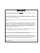
1.2 Warning Tags and Labels The warning tag illustrated below in Figure 1-1 is supplied with each hoist shipped from the factory. If the tag is not attached to your hoist’s pendant cord, order a tag from your dealer and install it. Read and obey all warnings attached to this hoist. Tag is not shown actual size.
2.0 Technical Information 2.1 Specifications 2.1.1 Product Code 2.1.2 SNER Models – Harrington SNER series hoists have a friction clutch mechanism that provides over winding protection. 2.1.
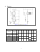
2.2 Dimensions Figure 2-1 Hoist Dimensions (See Table 2-2) Table 2-2 Hoist Dimensions Hoist Code Minimum Headroom: C L* a b d e g h i (ft) (in) (in) (in) (in) (in) (in) (in) 22.2 13.0 10.4 11.9 4.0 3.9 23.2 13.8 10.8 12.6 4.7 4.1 6.1 5.2 8.2 3.0 (in) SNER003S 13.8 7.2 SNER005L 14.0 7.2 SNER005S 14.6 7.2 SNER010L 16.1 7.2 SNER010S 17.3 7.2 SNER020L 22.6 7.2 SNER030C 29.5 8.2 0.9 1.2 26.9 16.5 12.6 14.4 1.5 1.
Table 2-3 Hook Dimension* T = Top Hook B = Bottom Hook Units = inch Capacity Code Hook a b c d e g T 1.1 0.7 0.9 0.7 1.4 1.1 B 1.1 0.7 0.9 0.7 1.4 0.9 010L, 010S T&B 1.4 0.9 1.2 0.9 1.7 1.2 020L T&B 1.9 1.1 1.6 1.1 2.0 1.5 030C T&B 2.2 1.4 1.9 1.4 2.4 1.7 003S, 005L, 005S *Refer to Section 5.7 for inspection dimensions and limits.
3.0 Preoperational Procedures 3.1 Fill Gear Box with Oil CAUTION 3.1.1 DO NOT use any oil or quantity other than that listed below. 3.1.2 For a new hoist the correct quantity and type of oil is supplied with the hoist in separate container(s). Remove the fill plug from the top of the hoist and connect the flexible pour tube to the oil container. Pour in all of the oil from the separate container(s), then replace the fill plug. 3.1.3 Refer to Section 6.
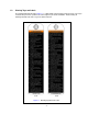
Figure 3-2 Chain Component Arrangement for Hoists with Upper Limit Switch Only. Figure 3-3 Chain Component Arrangement for Hoists with Optional Upper and Lower Limit Switch.
Figure 3-4 Attachment of Chain to Hoist Body – No Chain Container 3.2.3 3.2.4 When the optional canvas chain container is used, unfold it fully and install it on the hoist body as shown in Figure 3-5. In this case the free end of the chain is not attached to the hoist body and the chain stopper is installed on the third link from the free end. To place the chain into the chain container, feed the chain into the chain container beginning with the free end. Take care to avoid twisting or tangling the chain.
3.2.5 3.2.6 When using an optional steel chain container, refer to the assembly drawing and instructions provided with the container for correct assembly and attachment. WARNING Verify that the load chain is not twisted or tangled prior to operating the hoist. Make sure the bottom hook on 3 Ton double fall model is not capsized. See Figures 3-6 and 3-7. Correct all chain irregularities before conducting the first hoist operation.
3.4 3.5 Mounting the Hoist 3.4.1 Manual Trolley - Follow instructions in Owner’s Manual provided with the trolley. 3.4.2 Motorized Trolley - Follow instructions in Owner’s Manual provided with the trolley. 3.4.3 Hook Mounted to a Fixed Location - Attach the hoist’s top hook to the fixed suspension point. 3.4.4 WARNING Ensure that the fixed suspension point rests on the center of the hook’s saddle and that the hook’s latch is engaged. Electrical Connections 3.5.
Figure 3-8 Pendant and Power Supply Cable Hardwire Connections Figure 3-9 Pendant and Power Supply Cable Connections Power Supply Cable - Installation If the hoist is hook mounted to a fixed support ensure that the Power Supply Cable is properly installed and supported between the hoist and the electrical power supply. If the host is installed on a manual trolley, then the Power Supply Cable must be installed along the beam that the trolley runs on.
Figure 3-10 230V Jumper Wire Location 3.6 Preoperational Checks and Trial Operation 3.6.1 WARNING Confirm the adequacy of the rated capacity for all slings, chains, wire ropes and all other lifting attachments before use. Inspect all load suspension members for damage prior to use and replace or repair all damaged parts. WARNING 3.6.2 Verify and correct all chain irregularities prior to operating the hoist. Refer to Section 3.2. 3.6.3 Measure and record the “k” dimension of all hooks on hoist.
4.0 Operation 4.1 Introduction DANGER DO NOT WALK UNDER A SUSPENDED LOAD WARNING HOIST OPERATORS SHALL BE REQUIRED TO READ THE OPERATION SECTION OF THIS MANUAL, THE WARNINGS CONTAINED IN THIS MANUAL, INSTRUCTION AND WARNING LABELS ON THE HOIST OR LIFTING SYSTEM, AND THE OPERATION SECTIONS OF ANSI/ASME B30.16 and ANSI/ASME B30.10. THE OPERATOR SHALL ALSO BE REQUIRED TO BE FAMILIAR WITH THE HOIST AND HOIST CONTROLS BEFORE BEING AUTHORIZED TO OPERATE THE HOIST OR LIFTING SYSTEM.
The operation of an overhead hoist involves more than activating the hoist’s controls. Per the ANSI/ASME B30 standards, the use of an overhead hoist is subject to certain hazards that cannot be mitigated by engineered features, but only by the exercise of intelligence, care, common sense, and experience in anticipating the effects and results of activating the hoist’s controls.
CAUTION Improper operation of a hoist can create a potentially hazardous situation which, if not avoided, could result in minor or moderate injury, or property damage. To avoid such a potentially hazardous situation THE OPERATOR SHALL: • Maintain a firm footing or be otherwise secured when operating the hoist. • Use the hoist manufacturers recommended parts when repairing the unit. • Check brake function by tensioning the hoist prior to each lift operation.
5.0 Inspection 5.1 General 5.1.1 5.2 The inspection procedure herein is based on ANSI/ASME B30.16. The following definitions are from ANSI/ASME B30.16 and pertain to the inspection procedure below. Designated Person – a person selected or assigned as being competent to perform the specific duties to which he/she is assigned.
5.3 Frequent Inspection 5.3.1 Inspections should be made on a FREQUENT basis in accordance with Table 5-1, “Frequent Inspection.” Included in these FREQUENT Inspections are observations made during operation for any defects or damage that might appear between Periodic Inspections. Evaluation and resolution of the results of FREQUENT Inspections shall be made by a designated person such that the hoist is maintained in safe working condition.
5.5 Occasionally Used Hoists 5.5.1 5.6 5.7 Hoists that are used infrequently shall be inspected as follows prior to placing in service: Hoist Idle More Than 1 Month, Less Than 1 Year: Inspect per FREQUENT Inspection criteria in Section 5.3. Hoist Idle More Than 1 Year: Inspect per PERIODIC Inspection criteria in Section 5.4. Inspection Records 5.6.
Table 5-3 Hoist Inspection Methods and Criteria Item Method Criteria Action Hooks - Yoke Assembly Visual Should be free of significant rust, weld splatter, nicks, gouges. Holes should not be elongated, fasteners should not be loose, and there should be no gap between mating parts. Tighten or replace as required. Hooks - Swivel Bearing Visual, Function Bearing parts and surfaces should not show significant wear, and should be free of dirt, grime and deformations.
Table 5-3 Hoist Inspection Methods and Criteria Item Method Criteria Action Bolts, Nuts and Rivets Visual, Check with Proper Tool Bolts, nuts and rivets should not be loose. Tighten or replace as required. Motor Brake Measure, Visual Motor brake gap should be adjusted to the distance shown in Table 6-4 before measuring the brake wear. Brake lining dimension “A” should not be less than discard value listed in Table 5-6. Refer to Section 6.
Table 5-4 Top Hook & Bottom Hook Dimensions “k” Measured When New: Top: _________________________ Bottom: ______________________ "u" Dimension inch (mm) "t" Dimension inch (mm) Nominal "k" Dimension* inch (mm) Standard Discard Standard Discard 003S, 005L, 005S 1.65 (42) 0.93 (23.5) 0.83 (21) 0.69 (17.5) 0.63 (16) 010L, 010S 1.97 (50) 1.22 (31) 1.10 (28) 0.89 (22.5) 0.79 (20) 020L 2.46 (62.5) 1.57 (40) 1.42 (36) 1.14 (29) 1.02 (26) 030C 2.95 (75) 1.87 (47.5) 1.69 (43) 1.36 (34.
Table 5-6 Motor Brake Wear Dimensions NOTICE Brake must be properly adjusted before measuring "A". See Section 6.3 "A" Dimension - inch (mm) Capacity Code Standard Discard 003S, 005L 0.67 (17) 0.61 (15.5) 005S, 010L 0.85 (21.5) 0.79 (20) 010S, 020L, 030C 0.89 (22.5) 0.
6.0 Maintenance and Handling 6.1 Count/Hour Meter (Optional) 6.1.1 The optional Count/Hour (C/H) Meter located on the electrical control panel records the hoist's on time and number of starts. To view the two values press the button on the C/H Meter one time. The display will first show an "H" and a 4 digit number which is the hoist's total on time (up and down) in hours.
6.2 Lubrication 6.2.1 Load Chain For longer life, the load chain should be lubricated. The load chain lubrication should be accomplished after cleaning the load chain with an acid free cleaning solution. Apply Harrington lubricating grease (Part No. ER1BS1951) or an equivalent to industrial general lithium grease, NLGI No. 0, to the bearing surfaces of the load chain links as indicated by the shaded areas in Figure 6-2.
Change gear oil at least once every 5 years. The oil should be changed more frequently depending on the hoist's usage and operating environment. Refer to Section 6.1. Refer to Figure 3-1 and Table 3-1 to change the gear oil, remove both fill and drain plugs and allow the old oil drain completely. Replace the drain plug and refill the gear case with the correct quantity of new oil or until the oil level is within the range shown in Table 6-3. 6.
1) Bend the tab of the Lock Washer away from the Adjusting Nut so that the Adjusting Nut can be rotated. 2) Using a spanner wrench and a feeler gauge, rotate the Adjusting Nut to attain the proper Brake Gap per Table 6-4. 3) After the Brake Gap is set, secure the Adjusting Nut by bending one of the tabs of the Lock Washer into a slot in the Adjusting Nut. If necessary rotate the Adjusting Nut clockwise (tightening) to line up the tab with the slot.
6.3.5 6.4 Motor Brake Unit Installation - After the brake is properly adjusted and inspected, carefully replace the motor brake unit back into the hoist. Be sure to reseal the Motor Cover to motor frame surface using a small bead of liquid (hi-temperature) sealant. Refer to Section 6.3.2 and reassemble the parts in reverse order of removal. Load Chain 6.4.1 Lubrication and Cleaning – refer to Section 6.2. 6.4.
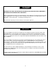
Figure 6-4 Chain Replacement 6.5 Friction Clutch 6.5.1 6.6 Storage 6.6.1 6.7 6.8 Friction Clutch – If abnormal operation or slippage occurs do NOT attempt to disassemble or adjust the Friction Clutch. Replace the worn or malfunctioning Friction Clutch as an assembly with a new, factory adjusted part. The storage location should be clean and dry. Outdoor Installation 6.7.1 For hoist installations that are outdoors, the hoist MUST BE covered and protected from the weather at all times. 6.7.
7.0 Troubleshooting WARNING HAZARDOUS VOLTAGES ARE PRESENT IN THE HOIST AND IN CONNECTIONS BETWEEN COMPONENTS. Before performing ANY troubleshooting on the equipment, de-energize the supply of electricity to the equipment, and lock and tag the supply device in the de-energized position. Refer to ANSI Z244.1, “Personnel Protection Lockout/Tagout of Energy Sources.” Only Trained and competent personnel should inspect and repair this equipment.
Table 7-1 Troubleshooting Guide Symptom Hoist will not operate (continued) Hoist lifts but will not lower Hoist lowers but will not lift Hoist will not lift rated load or does not have the proper lifting speed Load drifts excessively when hoist is stopped Cause Remedy Faulty Start Switch Disconnect Start Switch from motor. The resistance between the Start Switch terminals 2 and 3 should be greater than 500K ohms. If not, consult factory.
Table 7-1 Troubleshooting Guide Symptom Motor or brake overheating Hoist operates intermittently Cause Remedy Excessive load Reduce load to within rated capacity of hoist. Excessive duty cycle Reduce frequency of lifts. Wrong voltage or frequency Check voltage and frequency of power supply against the rating on the nameplate on the motor. Brake drags Check brake adjustment for proper clearance.
8.0 Material Safety Data Sheets NOTICE The SNER hoists are shipped new with the oil for the gear box in separate container(s). In compliance with OSHA regulations, Material Safety Data Sheets (MSDS) have been provided for the gear oil that is provided in this separate container. 8.1 SNER Model Gear Box Oil Material Safety Data Sheet (MSDS) SECTION I MANUFACTURER’S NAME Nippon Oil Co., Ltd.
SNER Model Gear Box Oil Material Safety Data Sheet (MSDS) - continued SECTION IV OCCUPATIONAL CONTROL PROCEDURES Eye protection: Chemical type goggles or face shield optional. Skin protection: Avoid prolonged or frequently repeated skin contact with wearing impervious protective clothing including gloves. Respiratory protection: Ventilation: Other clothing and equipment: No special respiratory protection is normally required. No special ventilation is usually necessary.
SNER Model Gear Box Oil Material Safety Data Sheet (MSDS) - continued SECTION VII Oral: Dermal: SECTION VIII MEDIAN LETHAL DOSE (LD50) N.D. ; Believed to be greater than 5g/kg (rat) ; Practically non-toxic N.D. ; Believed to be greater than 3g/kg (rabbit) ; Practically non-toxic FIRE PROTECTION INFORMATION Flash Point ºC 240 Autoignition Temp. ºC N. D. Flammability Limits N. D. Extinguishing Media: SECTION IX Carbon Dioxide (CO2), Dry chemical foam, Water fog, or spray.
SNER Model Gear Box Oil Material Safety Data Sheet (MSDS) - continued SECTION XII CHEMICAL AND PHYSICAL PROPERTIES Density 15ºC g/cm3 0.900 Viscosity C5t @40ºC 260 Solubility Insoluble in water Boiling point N. D. Evaporation rate N. D. Vapor pressure mmHg N. D. Vapor Density N. D. PH of undiluted product N. D. Percent Volatile by volume N. D. Appearance Green colored liquid Odor Little odor N. D.
8.2 SNER Model Load Chain Grease Material Safety Data Sheet (MSDS) Effective date: November 9, 1999 SECTION 1. MSDS No.
SNER Model Load Chain Grease Material Safety Data Sheet (MSDS) - continued SECTION 3. HAZARDS IDENTIFICATION EMERGENCY OVERVIEW Warning statement: Caution! Prolonged or repeated contact with skin may cause irritation in some cases. Precautionary Measures: Avoid breathing vapor and mist. Keep container closed. Avoid contact with eyes, skin, and clothing. Wash thoroughly after handling. Keep away from heat. Potential health effect: Eyes: May cause minor irritation.
SNER Model Load Chain Grease Material Safety Data Sheet (MSDS) - continued SECTION 6. ACCIDENTAL RELEASE MEASURES Procedures in Case of Accidental Release, Breakage, or Leakage: Stop the source of the leak or release. Clean up releases as soon as possible. Contain liquid to prevent further contamination of soil, surface water or groundwater. Clean up small spills using appropriate techniques such as absorbent materials or pumping. Where feasible and appropriate, remove contaminated soil.
SNER Model Load Chain Grease Material Safety Data Sheet (MSDS) - continued SECTION 10. STABILITY AND REACTIVITY Stability: Condition to Avoid: Incompatibility (materials to avoid): Hazardous Polymerization: Thermal decomposition: SECTION 11. Stable See the Handling and Storage section for further details. Acids. Oxidizing agents. Halogens and halogenated compounds. Will not occur. Smoke, carbon monoxide, aldehydes and other products of incomplete combustion.
SNER Model Load Chain Grease Material Safety Data Sheet (MSDS) - continued SECTION 15. REGULATION INFORMATION The U.S. TSCA inventory: The EC EINECS inventory: The CANADA DSL inventory: All components of this material are on the US TSCA inventory. May require notification before sale in US. No data available. All components of this material are on the EC EINECS inventory. May require notification before sale in EC. No data available. Some components of this material are on the EC ELINCS inventory.
9.0 Warranty All products sold by Harrington Hoists, Inc.
10.0 Parts List When ordering Parts, please provide the Hoist code number, lot number and serial number located on the Hoist nameplate (see fig. below). Reminder: Per sections 1.1 and 3.6.4 to aid in ordering Parts and Product Support, record the Hoist code number, lot number and serial number in the space provided on the cover of this manual. SNER Series Nameplate The parts list is arranged into the following sections: Section Page 10.1 Housing and Motor Parts……………………………………………….……………………………...48 10.
10.
Figure No.
Part Name Parts Per Hoist 003S 005L 005S 010L 37 Toothed Lock Washer 4 39 Oil Plug B 1 ER1BS9135 40 Eyebolt Packing 1 ES127005S 010S 9679709 020L 030C 9679711 41 Name Plate OF 1 ER1BS9890 43 Spring Pin 1 E3S129005S 44 Cover Suspender A 1 ER1BS9431 45 Cover Suspender B 1 ER1BS9432 46 Washer 2 ER1BS9436 47 Machine Screw with Lock Washer 2 48 Packing C 1 ER1BS9117 49 Controller Cover Assembly 1 ER1BB2104 50 Socket Bolt 4 51 Spring Washer 4 52 Name Pla
This Page Intentionally Left Blank 51
10.
Figure No.
10.
Figure No.
26 27 Part Name Parts Per Hoist Bottom Hook Complete Set 1 Bottom Hook Assembly 1 28 Hook Latch Assembly 003S ER1BS1011 005L 005S ER1CS1011 010L 010S 020L 030C ER1DS1011 ER1ES1011 ER1DR1011 ER1FS2011 1 ER1BS1002 ER1DS1002 ER1ES1002 ER1FS1002 ES026003 ES026010L ES026015 ES026025 29 Thrust Collar A 1 30 Hook Stopper 2 ES027003 ES027010L ES027015 ES027025 31 Thrust Bearing 1 ES022003 ES022010L ES022015 ES022025 32 Bottom Shaft Assembly 1 ES5054030 33 Idle Sheav
This Page Intentionally Left Blank
10.
Fig No Part Name Parts Per Hoist 1 Chain Guide A U 2 Chain Guide AL U/L 3 Guide Roller 4 Roller Pin 5 Limit Lever S 6 Limit Lever Assembly 7 Cushion Rubber 8 003S 005L 005S 010L 010S 1 ER1BS9331 ER1BL9331 ER1CS1331 ER1CL1331 ER1DS1331 ER1DL1331 1 ER1BS9330 ER1BL9330 ER1CS9330 ER1CL9330 ER1DS9330 ER1DL9330 1 1 9 Limit Lever Striker Chain Guide B 1 U/L 1 ER1BS5335 U (x) ER1BS9053 (2) U (x) U/L (x) U 1 1 11 Mach.
10.
Part Name Parts Per Hoist 003S 005L 005S 010L U 1 ER1BS1551 U/L 1 ER1BS2551 Socket Bolt 3 9091247 3 Spring Washer 3 4 Plate 1 5 Plate Screw 3 6 Hinge 1 1 Limit Switch Assembly 2 010S 020L 9012709 EP1BS9441 EP1CS9441 ER1BS9442 ER1CS9442 EP1DS9441 ER1BS9445 7 Hinge Screw 2 8 Mach. Screw w/Spring Washer 2 9 Bushing 1 11 Terminal Plate, 14P 1 ECP1314AA 12 Mach.
10.6 Power Supply and Pendant Parts 62 64 10.
Fig No Part Name Parts Per Hoist 003S 005L 005S 010L 1 Socket Holder 1 ER1BS9513 2 Socket Holder Packing 1 ER1BS9512 3 Machine Screw with Spring Washer 4 ES656003 4 Cable Support Arm 1 ER1BS9541 5 Machine Screw with Spring Washer 2 ES650005S 6 Tapping Machine Screw 4 7 Power Supply Cable 3C Complete Set 1 010S 020L 030C ER1BS9517 EP1BS1521 EP1CS1521 8 Holder Plate 1 ECP5924AI 9 Plate Packing 1 ECP5924AJ 10 Cable Hanger 14 Assembly 2 11 Power Supply Cable 1
www.harringtonhoists.com Harrington Hoists, Inc. 401 West End Avenue Manheim, PA 17545-1703 Phone: 717-665-2000 Toll Free: 800-233-3010 Fax: 717-665-2861 Harrington Hoists – Western Division 2341 Pomona Rd.