EFFECTIVE: November 21, 2003 Owner's Manual MOTORIZED TROLLEY SMR SERIES MODELS MP1A & MP1B 1 Ton through 3 Ton Capacity Code, Lot and Serial Number WARNING This equipment should not be installed, operated or maintained by any person who has not read and understood all the contents of this manual. Failure to read and comply with the contents of this manual can result in serious bodily injury or death, and/or property damage.
Table of Contents Section 1.0 2.0 3.0 4.0 5.0 Page Number Important Information and Warnings………………………………………………………………………. 4 1.1 Terms and Summary 1.2 Warning Tags and Labels Technical Information ………………………………………………………………………………………. 8 2.1 Specifications 2.2 Dimensions Pre-operational Procedures………………………………………………………………………………...10 3.1 Assembly and Adjustment 3.2 Mounting Location 3.3 Installation of Trolley onto Beam 3.4 Electrical Connections 3.
Section 6.0 Page Number Maintenance & Handling………………………………………………………………………………….. 33 6.1 Lubrication 6.2 Brake 6.3 Storage 6.4 Outdoor Installation 7.0 Troubleshooting……………………………………………………………………………………………. 34 8.0 Warranty……………………………………………………………………………………………………. 35 9.0 Parts List……………………………………………………………………………………………………. 37 9.1 Electric Parts 9.2 Pendant Parts 9.3 Power Supply Parts 9.4 Side Plates and Suspension Parts 9.
Important Information and Warnings 1.1 Terms and Summary This manual provides important information for personnel involved with the installation, operation and maintenance of this product. Although you may be familiar with this or similar equipment, it is strongly recommended that you read this manual before installing, operating or maintaining the product. Danger, Warning, Caution and Notice - Throughout this manual there are steps and procedures that can present hazardous situations.
WARNING Equipment described herein is not designed for and MUST NOT be used for lifting, supporting, or transporting people, or for lifting or supporting loads over people. Equipment described herein should not be used in conjunction with other equipment unless necessary and/or required safety devices applicable to the system, crane, or application are installed by the system designer, system manufacturer, crane manufacturer, installer, or user.
DANGER HAZARDOUS VOLTAGES ARE PRESENT IN THE CONTROL BOX, OTHER ELECTRICAL COMPONENTS, AND CONNECTIONS BETWEEN THESE COMPONENTS. Before performing ANY mechanical or electrical maintenance on the equipment, de-energize (disconnect) the main switch supplying power to the equipment; and lock and tag the main switch in the de-energized position. Refer to ANSI Z244.1, “Personnel Protection – Lockout/Tagout of Energy Sources”. Only trained and competent personnel should inspect and repair this equipment.
1.2 Warning Tag and Labels The warning tag illustrated below in Figure 1-1 is supplied with each trolley shipped from the factory. If the tag is not attached to the pendant cord for your hoist/trolley, order a tag from your dealer and install it. Read and obey all warnings attached to this trolley. Tag is not shown actual size.
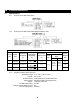
2.0 Technical Information 2.1 Specifications 2.1.1 Product Code for SMR Trolley Alone: 2.1.2 Product Code for SMR Trolley with SNER Series Electric Hoist: Table 2-1 Trolley Specifications Capacity (Ton) 1 Product Code SMR010L/S Standard Beam Flange Range Optional Beam Flange Range Min. Allowable Radius for Curve (in) (in) (in) 2.28 to 5.00 2 SMR020L/S 3.23 to 6.02 3 SMR030L/S 3.23 to 6.02 5.01 to 6.02 OR Motor Output (Hp) Current Draw* (amps) 115V 6.03 to 7.02 OR 31.5 7.
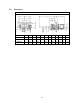
2.2 Dimensions Table 2-2 Trolley Dimensions Code b b' d e e' i j k m n r t SMR010L/S 12.4 15.6 10.6 20.3 7.0 3.74 0.9 5.1 8.0 4.3 2.0 1.22 SMR020L/S 12.8 16.4 10.7 20.5 7.2 4.33 1.1 4.9 8.3 4.6 2.4 1.42 SMR030L/S 13.4 17.4 10.8 20.5 7.3 4.92 1.1 5.2 8.5 5.2 2.7 1.
3.0 Pre-operational Procedures 3.1 Assembly and Adjustment 3.1.1 When the SMR trolley is combined with a hoist, follow and complete all pre-operational procedures provided with the hoist. For Harrington SNER model hoists, follow the pre-operational procedures in the SNER Owner's Manual in conjunction with all information provided in this section for mounting and electrical connections. 3.1.
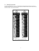
Suspender G Split Pin Connection Yoke Rubber Optional Connection Yoke Slotted Nut Yoke Bolt Connection Shaft Suspender T (Standard) Hoist Fixing Shaft Plate A (Retains Shaft) Controller Cover Assembly Machine Screw & Spring Washer Figure 3-1 Installing Suspender T or Connection Yoke on SNER Hoists – Up Through 1/4 to 2 Ton Capacity Suspender T (Standard) Suspender T (Standard) Suspender G (Optional) Yoke Bolt Suspender G (Optional) Slotted Nut & Split Pin Connection Yoke Note: Suspender G f
3.1.5 Trolley Assembly 1) Refer to Figure 3-3. 2) Remove the Shaft Stopper Pin, Side Plate S, and Spacers from the Suspension Shaft. For beam flanges that are wider than the standard range, different suspension shaft and/or spacer arrangements are provided. Refer to Table 3-1. 3) Insert the Suspension Shaft to Side Plate G and attach it with the Suspension Shaft Bolt, Slotted Nut and Split Pin (cotter pin). Refer to Figure 3-5 and insure that correct Suspension Shaft holes are used.
Figure 3-5 Suspension Shafts 3.1.6 Adjusting the trolley width - After assembling trolley per Section 3.1.5, check the adjustment as follows: 1) Refer to Figure 3-6. 2) Make sure both side plates are spread fully outward and Measure Dimension "A". Dimension "A" must be 1/8 to 3/16" greater than "B". For trolleys up through 3 Ton.
Note: Inner Spacer rows on Table 3-2 list two numbers. First number is the quantity of spacers located on the left side of the Suspender or Suspension Plates, second number is the quantity on the right side.
3 and 2 1 3 Outer Inner Outer Inner 0+0 5 2 2 0 1+1 3 0+0 7 1+0 76 75 0 1+1 3 0+0 5 1+2 82 3 14 0+0 2 0+0 2 Inner Outer Thick Inner L Outer Fixing 3 3 Outer Thick 3 0+0 5 0+0 2+3 0 1+1 3 0+0 3 2+3 91 90 2 0+0 3 0+0 1 3+4 0 1+1 1 1+1 8 0 98 0 1+1 3 0+0 8 0 0 1+1 1 1+1 7 1+0 100 3 9 16 3 7 8 315 16 Inner 1+2 0+0 3 0+0 0 0+0 3 0+0 3 4+4 74 66 2+3 73
(in) 3 and 2 1 1+1 Inner 0 1+1 0 0 Inner Outer 9 0 1+1 Outer 5 0+0 1+1 9 Inner 1+1 6 0+0 Outer Thick Inner L Outer Fixing Thick Thin 0 1+2 0 1+1 Inner 1+1 0 1+1 9 0+0 1+1 0 9 Outer 0+0 Inner Outer 5 1+2 185 181 6 184 180 1+1 7 5 16 7 18 Inner 7 14 7 116 Outer Thick Inner L Outer Fixing Thick Thin Cap.
3.1.7 Counter Weight – For proper balance 1 Ton, SMR trolleys require a Counter Weight when installed on a 3 7/8 inch or smaller beam flange. The Counter Weight mounts on the Suspension Shaft as shown in Figure 3-9 and is held in place with a Bolt, Slotted Nut and Split Pin. The bolt is installed through holes B and C. Make sure the weight is securely fastened to the shaft and that the split pin is properly bent. All other trolley capacities do NOT require a counter weight.
Figure 3-10 Optional trolley installation method 3.4 Electrical Connections 3.4.1 CAUTION 3.4.2 CAUTION 3.4.3 3.4.4 3.4.5 Ensure that the voltage of the electric power supply is proper for the hoist or trolley. Do NOT apply electronic soft-start control or voltage varying controls to the SMR trolley. Use of such devices may cause the motor brake and other electrical components to malfunction.
Figure 3-12 Pendant Cord Cable Terminal Connections.
Power Supply Cable Hoist Connection – The Power Supply Cable connects directly to the trolley's Switch Box using Cable Holder Assembly. Make this connection as follows: 1) Refer to Figure 3-14 2) With 1 inch of the outer cable insulation extending beyond the cable packing, insert the cable into the switch box and screw together Cable Holder A and B. 3) Refer to Figure 3-14 and connect the black and white wires to terminals 1 and 2 on the terminal strip inside the Switch Box.
Figure 3-14 Power Supply Cable Terminal Connections. Figure 3-15 Trolley to Hoist Terminal Connections 3.4.8 DANGER Grounding - An improper or insufficient ground connection creates an electrical shock hazard when touching any part of the hoist or trolley. In the Power Supply Cable the ground wire will be either Green with Yellow stripe or solid Green. It should always be connected to a suitable ground connection. Do not paint the trolley wheel running surfaces of the beam as this can affect grounding.
Figure 3-16 Power Supply Cable installation and Guide Wire location.
3.5 Pre-operational Checks and Trial Operation 3.5.1 Refer to the trolley's Nameplate and record the Code, Lot and Serial Number in the space provided on the cover of this manual. 3.5.2 Refer to the hoist's owner's manual and perform all pre-operational checks for the hoist. 3.5.3 Perform pre-operational checks for the trolley: Confirm the adequacy of the rated capacity for all slings, chains, wire ropes and all other lifting attachments before use.
4.0 Operation 4.1 Introduction DANGER DO NOT WALK UNDER A SUSPENDED LOAD WARNING HOIST OPERATORS SHALL BE REQUIRED TO READ THE OPERATION SECTION OF THIS MANUAL, THE WARNINGS CONTAINED IN THIS MANUAL, INSTRUCTION AND WARNING LABELS ON THE HOIST OR LIFTING SYSTEM, AND THE OPERATION SECTIONS OF ANSI/ASME B30.16 and ANSI/ASME B30.10. THE OPERATOR SHALL ALSO BE REQUIRED TO BE FAMILIAR WITH THE HOIST AND HOIST CONTROLS BEFORE BEING AUTHORIZED TO OPERATE THE HOIST OR LIFTING SYSTEM.
The operation of an overhead hoist involves more than activating the hoist’s controls. Per the ANSI/ASME B30 standards, the use of an overhead hoist is subject to certain hazards that cannot be mitigated by engineered features, but only by the exercise of intelligence, care, common sense, and experience in anticipating the effects and results of activating the hoist’s controls.
CAUTION Improper operation of a hoist can create a potentially hazardous situation which, if not avoided, could result in minor or moderate injury, or property damage. To avoid such a potentially hazardous situation THE OPERATOR SHALL: • Maintain a firm footing or be otherwise secured when operating the hoist. • Use the hoist manufacturer’s recommended parts when repairing the unit. • Check brake function by tensioning the hoist prior to each lift operation.
5.0 Inspection 5.1 General 5.1.1 5.2 The inspection procedure herein is based on ANSI/ASME B30.16. The following definitions are from ANSI/ASME B30.16 and pertain to the inspection procedure below. n Designated Person - a person selected or assigned as being competent to perform the specific duties to which he/she is assigned.
5.3 Frequent Inspection 5.3.1 Inspections should be made on a FREQUENT basis in accordance with Table 5-1, “Frequent Inspection.” Included in these FREQUENT Inspections are observations made during operation for any defects or damage that might appear between Periodic Inspections. Evaluation and resolution of the results of FREQUENT Inspections shall be made by a designated person such that the trolley is maintained in safe working condition.
5.7 Inspection Methods and Criteria 5.7.1 This section covers the inspection of specific items. The list of items in this section is based on those listed in ANSI/ASME B30.16 for Frequent and Periodic Inspection. In accordance with ANSI/ASME B30.16, these inspections are not intended to involve disassembly of the trolley. Rather, disassembly for further inspection would be required if frequent or periodic inspection results so indicate.
Table 5-3 Trolley Inspection Methods and Criteria Item Method Criteria Action Pendant - Switches Function Depressing and releasing push buttons should make and break contacts in switch contact block and result in corresponding electrical continuity or open circuit. Push-buttons should be interlocked either mechanically or electrically to prevent simultaneous energization of circuits for opposing motions (e.g. forward and reverse). Repair or replace as necessary.
Table 5-4 Track Wheel Wear Dimensions Note: Track wheels are for flat and tapered flanges. “d” Dimension inch (mm) Capacity (Ton) “D” Dimension inch (mm) Standard Discard Standard Discard 1 3.60 (91.5) 3.44 (87.5) 3.74 (95) 3.58 (91) 2 4.17 (106) 3.98 (101) 4.33 (110) 4.13 (105) 3 4.76 (121) 4.49 (114) 4.92 (125) 4.65 (118) Table 5-5 Side Roller Wear Dimensions Trolley Side Plate DIA.
Table 5-6 Motor Brake Wear Dimensions Capacity (Ton) 1, 2 and 3 "A" Dimension - inch (mm) Model Standard Discard MP1A 1.45 (36.8) 1.38 (35.3) MP1B 1.25 (31.8) 1.19 (30.
6.0 Maintenance & Handling 6.1 Lubrication 6.2 6.1.1 Lubricate the following trolley components with NLGI (National Lubricating Grease Institute) #2 or equivalent grease. 6.1.2 Track Wheel Gear – Clean and re-grease the Track Wheel gears and motor output pinion every three months (more frequently for heavier usage or severe conditions). Do not use an excessive amount of grease and avoid getting any grease on the running surfaces of the Track Wheels or the beam. 6.1.
7.0 Troubleshooting WARNING HAZARDOUS VOLTAGES ARE PRESENT IN THE TROLLEY AND IN CONNECTIONS BETWEEN COMPONENTS. Before performing ANY maintenance on the equipment, de-energize the supply of electricity to the equipment, and lock and tag the supply device in the de-energized position. Refer to ANSI Z244.1, “Personnel Protection – Lockout/Tagout of Energy Sources.” Only Trained and competent personnel should inspect and repair this equipment.
8.0 Warranty Warranty explanation and terms. All products sold by Harrington Hoists, Inc.
This Page Intentionally Left Blank 36
9.0 1/8 to 3 Ton Parts List* When ordering Parts, please provide the Hoist code number, lot number and serial number located on the Hoist nameplate (see fig. below). Reminder: Per sections 1.1 and 3.5.1 to aid in ordering Parts and Product Support, record the Hoist code number, lot number and serial number in the space provided on the cover of this manual. SMR Series Nameplate The parts list is arranged into the following sections: Section 9.1 9.2 9.3 9.4 9.5 Page Electric Parts………………………….
9.
9.1 Electric Parts Figure No.
9.
9.2 Pendant Parts Part Name Parts Per Trolley Bar Holder Assembly 1 2 Bar Holder 1 MR1DS9481 3 Cord Chain Stopper 1 E6L614010S 4 Machine Screw w/Spring Washer 2 E6F151003 5 Spring Washer 2 9012712 6 Socket Bolt 2 9091295 7 Machine Screw w/Spring Washer 4 MS554010 8 Figure No.
9.
9.3 Power Supply Parts Figure No.
9.
9.4 Side Plates and Suspension Parts – All Speeds Figure No.
9.
9.5 Motor Parts Figure No.
www.harringtonhoists.com Harrington Hoists, Inc. 401 West End Avenue Manheim, PA 17545-1703 Phone: 717-665-2000 Toll Free: 800-233-3010 Fax: 717-665-2861 Harrington Hoists – Western Division 2341 Pomona Rincon Rd.