EFFECTIVE: November 4, 2009 Owner’s Manual MANUAL TROLLEY HOIST MODEL SHB 1 Ton through 10 Ton Capacity Code, Lot and Serial Number WARNING This equipment should not be installed, operated or maintained by any person who has not read and understood all the contents of this manual. Failure to read and comply with the contents of this manual can result in serious bodily injury or death, and/or property damage.
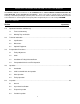
IMPORTANT INFORMATION ON HOW TO USE THIS MANUAL This OWNER’S MANUAL is intended for use in combination with the “Owner’s Manual for Manual Chain Hoist CB Series Model M3 1/2 Ton through 20 Ton Capacity”. Refer to the Table of Contents below to determine the location(s) of information pertaining to your trolley hoist. References to the “Owner’s Manual for Manual Chain Hoist CB Series Model M3 1/2 Ton through 20 Ton Capacity” will be designated by the use of the acronym “M3CBOM”. Table of Contents Section 1.
Section 6.0 Page Number 5.5 Occasionally Used Hoists 5.6 Inspection Records 5.7 Inspection Methods and Criteria Maintenance & Handling …………………………………………………………………………………. 31 6.1 Lubrication 6.2 Storage 6.3 Outdoor Installation 6.4 Operational Environment 7.0 Troubleshooting …………………………………………………………………………………………… 32 8.0 Warranty …………………………………………………………………………………………………… 34 9.
1.0 Important Information and Warnings 1.1 Terms and Summary This manual provides important information for personnel involved with the installation, operation and maintenance of this product. Although you may be familiar with this or similar equipment, it is strongly recommended that you read this manual before installing, operating, or maintaining the product. Danger, Warning, Caution, and Notice Throughout this manual there are steps and procedures that can present hazardous situations.
WARNING Equipment described herein is not designed for and MUST NOT be used for lifting, supporting, or transporting people, or for lifting or supporting loads over people. Equipment described herein should not be used in conjunction with other equipment unless necessary and/or required safety devices applicable to the system, crane, or application are installed by the system designer, system manufacturer, crane manufacturer, installer, or user.
NOTICE It is the responsibility of the owner/user to install, inspect, test, maintain, and operate a trolley or hoist in accordance with ANSI/ASME B30.16, “Safety Standard for Overhead Hoists”, OSHA Regulations and ANSI/NFPA 70, "National Electric Code". If the trolley is installed as part of a total lifting system, such as an overhead crane or monorail, it is also the responsibility of the owner/user to comply with the applicable ANSI/ASME B30 volume that addresses that type of equipment.
1.2 Warning Tags and Labels The warning tag illustrated below in Figure 1-1 is supplied with each hoist shipped from the factory. If the tag is not attached to your trolley hoist’s no-load side of the load chain, order a tag from your dealer and install it. Read and obey all warnings attached to this hoist. Tag is not shown actual size.
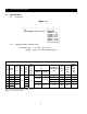
2.0 Technical Information 2.1 Specifications 2.1.1 Product Code 2.1.2 Operating Conditions and Environment Temperature range: Humidity: -4° to +140°F (-20° to +60°C) 100% or less (Not an Underwater Device) Table 2-1 SHB Trolley Hoist Specifications Cap. Product (Tons) Code Headroom Std C Lift1 (in) (ft) Pull to Lift Load (lbs) 1 SHB010 4.5 64 2 SHB020 5.7 58 3 SHB030 6.5 5 SHB050 7.7 8 SHB080 10 SHB100 10.0 20 74 90 Min.
2.2 Dimensions Table 2-2 SHB Trolley Hoist Dimensions Cap. b1 b2 d e1 e2 f g h i j k m n1 n2 q r s t u v (Tons) Product Code (in) (in) (ft) (in) (in) (in) (in) (in) (in) (in) (in) (in) (in) (in) (in) (in) (in) (in) (in) (in) 1 SHB010 8.0 13.5 19.3 7.9 7.0 19.3 1.1 4.17 2.80 1.0 4.5 8.7 5.9 11.4 14.6 1.8 B-1.6 1.22 2 SHB020 9.6 15.7 8.9 7.6 1.4 5.00 3.35 1.2 6.6 9.9 7.1 13.2 17.3 2.1 B-2.0 1.42 3 SHB030 11.6 18.3 9.5 8.
Table 2-3 Bottom Hook Dimension* B = Bottom Hook Units = inch (mm) Cap. (Tons) Product Code a b c d e g 1 SHB010 1.0 (26) 0.6 (16) 0.9 (22) 0.6 (16) 1.7 (43) 1.1 (29) 2 SHB020 1.4 (36) 0.9 (22) 1.2 (30) 0.9 (22) 2.0 (50) 1.4 (36) 3 SHB030 1.8 (45) 1.1 (27) 1.5 (38) 1.1 (27) 2.2 (56) 1.7 (43) 5 SHB050 2.2 (56) 1.4 (35) 1.9 (48) 1.4 (35) 2.5 (63) 1.8 (47) 8 SHB080 3.3 (83) 2.2 (55) 2.9 (73) 1.9 (48) 3.3 (85) 2.4 (62) 10 SHB100 3.3 (83) 2.2 (55) 2.
3.0 Preoperational Procedures 3.1 Trolley Adjustment NOTICE 3.1.1 Before use, the trolley can be adjusted in increments of 1/8” by simply inserting or removing adjusting spacers to fit a variety of beam flanges. Adjustments must be made to the Upper Suspension Shaft and to the Lower Suspension Shaft. 3.1.2 To adjust the Upper Suspension Shaft reference Figure 3-1 and Table 3-2. Proceed with the following instructions: 1. Remove all of the suspension shaft bolts. 2.
Table 3-2 Number of Adjusting Spacers - Upper Suspension Shaft Beam Flange Width (in) 2 5 2 1 2 58 2 7 8 16 2 Cap Spacer (mm) (Ton) Type 58 Inner 1 Thin 1 Thick Fixing C Thin 2 Thick Fixing 12 Thin 3 Thick Fixing Thin 5 Thick Fixing Thin 8 & 10 Thick Fixing Outer 1+3 Inner 1 Outer 1+3 Inner 1 Outer 0+1 Inner 2 64 66 73 3 76 31 4 82 37 39 8 16 91 98 315 16 4 100 102 47 43 16 16 4 1116 41516 106 119 113 125 5 127 3 5 1 55 57 55 53 16 5 8 16 2 8 8 131 135 137 14
Table 3-2 Number of Adjusting Spacers - Upper Suspension Shaft (Continued) Beam Flange (in) Width 611 16 Cap Spacer (mm) 170 (Ton) Type Thin 1 Thick Fixing C Thin 2 Thick Fixing 13 Thin 3 Thick Fixing Thin 5 Thick Fixing Thin 8 & 10 Thick Fixing Inner 9 Outer 1+1 Inner 0 Outer 1+6 Inner 3 Outer 0+1 Inner 2 Inner 5 Outer 3+2 Inner 2 Outer 1+1 Inner 4 Outer 0+0 Inner 5 Outer 3+3 Inner 2 Outer 1+1 Inner 4 Outer 0+0 Inner 4 Outer 3+2 Inner 67 8 175 7 71 16 71 178 180
Table 3-3 Number of Adjusting Spacers – Lower Suspension Shaft Beam Flange Width (in) Cap Spacer (mm) (Ton) Type Thin 1 Thick Fixing Thin 2 Thick Fixing Thin 14 3 Thick Fixing Thin 5 Thick Fixing Thin 8 & 10 Thick Fixing 2 5 2 1 2 58 2 7 8 16 2 3 31 4 37 39 8 16 315 16 4 47 43 16 16 4 1116 41516 5 3 5 1 55 57 55 53 16 5 8 16 2 8 8 6 7 6 3 65 16 16 6 16 58 64 66 73 76 82 91 98 100 102 106 113 119 125 127 131 135 137 140 143 150 153 157 160 163 6+7 Inner 1+2
Table 3-3 Number of Adjusting Spacers – Lower Suspension Shaft Beam Flange (in) Width 611 16 67 8 7 71 16 71 4 77 8 8 87 8 Cap Spacer (mm) 170 (Ton) Type 175 178 180 184 200 203 215 Thin 1 Thick Fixing Thin 2 Thick Fixing Thin 15 3 Thick Fixing Thin 5 Thick Fixing Thin 8 & 10 Thick Fixing 811 16 9 220 229 91 8 232 97 8 10 10 1 250 254 257 3 1 1 8 10 4 10 8 10 2 260 264 267 1 11 3 11 5 11 3 11 7 8 11 4 8 8 4 8 11 11 1 279 283 286 289 295 298 302 12
3.2 Chain 3.2.1 WARNING Verify that the load chain is not twisted or tangled prior to operating the hoist. Make sure the bottom hook is not capsized. See Figure 3-2 and Figure 3-3. Correct all chain irregularities before conducting the first trolley hoist operation. Figure 3-2 Twist in Load Chain – Double Fall Model Figure 3-3 Capsized Hook and Chain – Double Fall Model 3.2.
3.2.3 CAUTION Each chain container indicates the maximum length of the load chain that can be stored in the container. The amount of chain the container must hold is equal to the lift on the hoist. DO NOT use a chain container with a storage capacity less than the lift length on the hoist. Canvas Chain Container Figure 3-4 Attachment of Optional Canvas Chain Container to Hoist Body 3.2.4 3.
Figure 3-5 Mounting Trolley Hoist on Beam End 3.3.3 Optional Method for the Trolley Hoist – If the trolley hoist cannot be mounted from the end of the beam, complete the installation as follows: 1) Remove the Shaft Stopper Pin from Suspension Shaft (See Figure 3-6). 2) If possible remove the outside Adjusting spacers and Reinsert the Shaft Stopper Pin. Spread the trolley side plates apart. 3) Lift the trolley onto the beam so that Side Plate G (handwheel side) rests on the beam's flange.
3.4 Preoperational Checks and Trial Operation 3.4.1 WARNING Confirm the adequacy of the rated capacity for all slings, chains, wire ropes and all other lifting attachments before use. Inspect all load suspension members for damage prior to use and replace or repair all damaged parts. WARNING 3.4.2 Verify and correct all chain irregularities prior to operating the trolley hoist. Refer to Section 3.1. 3.4.3 Measure and record the “k” dimension of the hook on the trolley hoist.
4.0 Operation 4.1 Introduction DANGER DO NOT WALK UNDER A SUSPENDED LOAD WARNING HOIST OPERATORS SHALL BE REQUIRED TO READ THE OPERATION SECTION OF THIS MANUAL, THE WARNINGS CONTAINED IN THIS MANUAL, INSTRUCTION AND WARNING LABELS ON THE HOIST OR LIFTING SYSTEM, AND THE OPERATION SECTIONS OF ANSI/ASME B30.16 and ANSI/ASME B30.10. THE OPERATOR SHALL ALSO BE REQUIRED TO BE FAMILIAR WITH THE HOIST AND HOIST CONTROLS BEFORE BEING AUTHORIZED TO OPERATE THE HOIST OR LIFTING SYSTEM.
The operation of a hoist involves more than activating the hoist’s controls. Per the ANSI/ASME B30 standards, the use of a hoist is subject to certain hazards that cannot be mitigated by engineered features, but only by the exercise of intelligence, care, common sense, and experience in anticipating the effects and results of activating the hoist’s controls. Use this guidance in conjunction with other warnings, cautions, and notices in this manual to govern the operation and use of your hoist. 4.
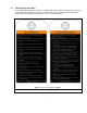
CAUTION Improper operation of a hoist can create a potentially hazardous situation which, if not avoided, could result in minor or moderate injury, or property damage. To avoid such a potentially hazardous situation THE OPERATOR SHALL: worn parts, and keep appropriate records of maintenance. • Maintain a firm footing or be otherwise secured when operating the hoist. • Check brake function by tensioning the hoist prior to each lift operation.
4.4 Trolley Operation 1) For Plain Trolley, movement is controlled by pushing/pulling on the load or the hook of the attached hoist. 2) For Geared Trolley, when facing Trolley hand chain wheel: 3) Pull down on the right side of Trolley hand chain (Clockwise Rotation) to move the Trolley left. Pull down on the left side of Trolley hand chain (Counterclockwise Rotation) to move the Trolley right. CAUTION Avoid collisions with the end stops or other Trolleys. Damage may result.
5.0 Inspection 5.1 General 5.1.1 5.2 The inspection procedure herein is based on ANSI/ASME B30.16. The following definitions are from ANSI/ASME B30.16 and pertain to the inspection procedure below. Designated Person – a person selected or assigned as being competent to perform the specific duties to which he/she is assigned.
5.3 Frequent Inspection 5.3.1 Inspections should be made on a FREQUENT basis in accordance with Table 5-1, “Frequent Inspection.” Included in these FREQUENT Inspections are observations made during operation for any defects or damage that might appear between Periodic Inspections. Evaluation and resolution of the results of FREQUENT Inspections shall be made by a designated person such that the hoist is maintained in safe working condition.
5.5 Occasionally Used Hoists 5.5.1 5.6 5.7 Trolley-hoists that are used infrequently shall be inspected as follows prior to placing in service: Trolley-hoist Idle More Than 1 Month, Less Than 1 Year: Inspect per FREQUENT Inspection criteria in Section 5.3. Trolley-hoist Idle More Than 1 Year: Inspect per PERIODIC Inspection criteria in Section 5.4. Inspection Records 5.6.
Table 5-3 Hoist Inspection Methods and Criteria Item Method Discard Limit/Criteria Action Hook – Bent Shank or Neck Visual Shank and neck portions of hook should be free of deformations. Replace. Hook – Swivel Visual, Function Bearing parts and surfaces should not show significant wear, and should be free of dirt, grime, and deformations. Hook should rotate freely with no roughness. See Figure 5-1. Clean/lubricate, or replace as required.
Table 5-3 Hoist Inspection Methods and Criteria Item Method Discard Limit/Criteria Housing and Mechanical Components Visual, Auditory, Function Trolley hoist components including suspension shafts, track wheels, track wheel axles, load blocks, suspension housing, chain attachments, clevises, yokes, suspension bolts, shafts, gears, bearings, stripper, pins, rollers, and bumpers should be free of cracks, distortion, significant wear, and corrosion.
Table 5-4 Bottom Hook Dimensions “k” Measured When New: Bottom: ______________________ Product Code 1.92 (48.8) 2.36 (59.9) 2.72 (69.1) 3.06 (77.8) "u" Dimension inch (mm) Standard Discard 0.86 (21.8) 0.77 (19.6) 1.18 (30.0) 1.06 (27.0) 1.48 (37.5) 1.33 (33.8) 1.87 (47.5) 1.69 (42.8) "t" Dimension inch (mm) Standard Discard 0.63 (16.0) 0.57 (14.4) 0.86 (21.8) 0.77 (19.6) 1.07 (27.2) 0.97 (24.5) 1.36 (34.5) 1.22 (31.1) 4.03 (102.3) 2.88 (73.0) 1.87 (47.
Table 5-6 Track Wheel Wear Dimensions Note: Track wheels are for flat and tapered flanges. Capacity (Ton) “D” Dimension inch (mm) Standard Discard “t” Dimension inch (mm) Standard Discard “r” Dimension inch (mm) Standard Discard 1 2.80 (71) 2.74 (69.5) 0.374 (9.5) 0.264 (6.7) 0.224 (5.7) 0.158 (4.0) 2 3.35 (85) 3.29 (83.5) 0.413 (10.5) 0.291 (7.4) 0.232 (5.9) 0.161 (4.1) 3 3.94 (100) 3.88 (98.5) 0.453 (11.5) 0.319 (8.1) 0.260 (6.6) 0.181 (4.6) 5 4.65 (118) 4.41 (112) 0.591 (15.
6.0 Maintenance and Handling 6.1 Lubrication 6.1.1 Load Chain For longer life, the load chain should be lubricated. The load chain lubrication should be accomplished after cleaning the load chain with an acid free cleaning solution. Apply Harrington lubricating grease (Part No. ER1BS1951) or an equivalent to industrial general lithium grease, NLGI No. 0, to the bearing surfaces of the load chain links as indicated by the shaded areas in Figure 6-1.
6.1.4 Hoist: 6.1.5 6.2 Follow the hoist lubrication instructions in the “Owner’s Manual for Manual Chain Hoist CB Series Model M3 1/2 Ton through 20 Ton Capacity” for further hoist information. Trolley: Lubricate the following trolley components with NLGI (National Lubricating Grease Institute) #2 or equivalent grease. Track Wheel Gear – Clean and re-grease the Track Wheel gears and Hand Wheel output pinion every three months (more frequently for heavier usage or severe conditions).
7.0 Troubleshooting WARNING Read and comply with instructions in this manual and use the trolley hoist properly. Checking the sounds from the hoist in operation is a critical inspection. Note trolley and hoist sounds during operation. If a defect is found in the trolley or the hoist, stop using immediately and check the cause of the defect. Only Trained and competent personnel should inspect and repair the hoist.
8.0 Warranty Warranty explanation and terms. All products sold by Harrington Hoists, Inc.
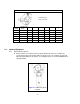
9.0 Parts List When ordering Parts, please provide the Trolley Hoist code number, lot number and serial number located on the Trolley Hoist nameplate (see fig. below). Reminder: Per sections 1.1 and 3.4.4, to aid in ordering Parts and Product Support, record the Trolley Hoist code number, lot number and serial number in the space provided on the cover of this manual. SHB Series Nameplate The parts list is arranged into the following sections: Section Page 9.1 SHB Parts (1 to 5 Ton) . . . . . . . . . . .
9.
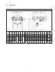
9.1 SHB Parts (1 to 5 Ton) Figure No.
9.
9.2 SHB Parts (8 and 10 Ton) Figure No.
This Page Intentionally Left Blank 40
This Page Intentionally Left Blank 41
This Page Intentionally Left Blank 42
This Page Intentionally Left Blank 43
www.harringtonhoists.com Harrington Hoists, Inc. 401 West End Avenue Manheim, PA 17545-1703 Phone: 717-665-2000 Toll Free: 800-233-3010 Fax: 717-665-2861 Harrington Hoists – Western Division 2341 Pomona Rd.