
Manual
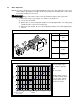

c) Reassemble as follows:
(1) During re-assembly be careful not to pinch the lead wires when assembling the
electromagnetic coil 5610.
(2) Assemble the motor with the brake disc 512 and armature 513. Ensure that the brake
disk is properly oriented and not backwards when installing. (Flat side facing AWAY from
motor)
(3) Insert the Spring Holder 605 and the Brake Spring 606 into the center recess of the
Electromagnetic Coil Assembly 5610.
(4) Re-assemble the Electromagnetic Coil Assembly 5610 onto the motor ensuring that the
Spring Holder 605 and the Brake Spring 606 remain inserted properly. Fasten using
Socket Bolts 607.
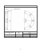
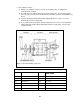
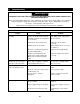
Figure 7-1 Structural drawing of gear motor
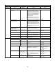
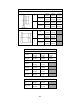
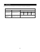
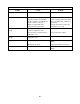
Table 7-1 Part List for Gear Motor
Part No. Part name Part No.
Part name
303 Gear box A 5610 Electromagnetic coil assembly
313 Socket bolt 603 Adjusting bolt
401 Gear box B 604 Lock nut
512 Brake disk 605 Spring holder
513 Armature 606 Brake spring
310 Gear box packing 607 Socket bolt
46