
Manual

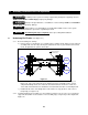

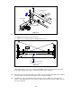

RUNWAY BEAM
BRI DGE BEAM
TEMP SUPPORT
Figure 3-2
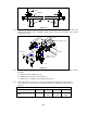
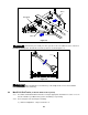
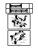
3.1.3 Install the remaining frames on the crane bridge and install the end brackets on both ends of the
end trucks (See Figure 3-3). Install pinion shafts, pinions, and collars (See Figure 3-3). Geared
and motorized only.
Runway Beam
End Truck Frames A & B
Bridge Beam
Pillow Blocks
Pinions & Collars
Figure 5 & 6
End Bracket
Figure 3-3
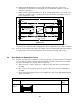
3.1.4 With the temporary support method of 3.1.2 above still in place refer to Figure 3-4 and check the
following:
a) End truck frames parallel; (A = B).
b) Bridge beam centered on each end truck.
c) Squareness of end trucks to the bridge beam; (X = Y).
3.1.5 Make adjustments as necessary. Then securely tighten and double nut each fastened
connection of the end truck frames to bridge beam. Refer to tightening torque values of
Table 3-1.
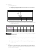
Table 3-1 Tightening Torque
Bolt Size M12 M14 M16 M20
Tightening Torque kg-cm
(ft-lbs)
1150
(83)
2580
(187)
5070
(366)
25