EFFECTIVE: March 18, 2014 END TRUCKS Top Running & Underhung SERIES 3 1 Ton through 10 Ton Capacity Model and Serial Number This equipment should not be installed, operated, or maintained by any person who has not read and understood all the contents of this manual. Failure to read and comply with the contents of this manual can result in serious bodily injury or death, and/or property damage.
INSTALLATION, OPERATION, MAINTENANCE AND PARTS MANUAL FOR SERIES 3 END TRUCKS Series 3 Top Running and Underhung End Trucks Thank you for selecting Harrington’s Series 3 End Trucks for your material handling needs. We believe the Series 3 End Truck will provide you years of trouble-free service when properly maintained. Further, by applying the information in this manual, you will obtain dependable performance from our products.
Table of Contents Section 1.0 2.0 3.0 Page Number Important Information and Warnings………………………………………………………………………….5 1.1 Terms and Summary 1.2 Warning Tags and Labels Technical Information…………………………………………………………………………………………..8 2.1 Specifications for Underhung End Trucks 2.2 Specifications for Top Running End Trucks 2.3 Component Names 2.4 Bridge Crane Design Requirements Assembly, Installation and Test Trial Operation…………………………………………………………….24 3.1 Underhung End Trucks 3.
Section Page Number 5.7 Inspection Methods and Criteria 6.0 Lubrication…………………………………………………………………………………………………….. 44 7.0 Maintenance & Handling……………………………………………………………………………………...45 7.1 General 7.2 Gear Motor - Reduction Gear 7.3 Gear Motor - Brake 7.4 Brake Adjustment 7.5 Storage 7.6 Outdoor Installations 8.0 Troubleshooting……………………………………………………………………………………………….49 9.0 Warranty……………………………………………………………………………………………………….52 10.0 Parts List……………………………………………………………………………………………………….
1.0 1.1 Important Information and Warnings Terms and Summary This manual provides important information for personnel involved with the installation, operation and maintenance of this product. Although you may be familiar with this or similar equipment, it is strongly recommended that you read this manual before installing, operating, or maintaining the product. Danger, Warning, Caution, and Notice Throughout this manual, there are steps and procedures that can present hazardous situations.
Equipment described herein is not designed for and MUST NOT be used for lifting, supporting, or transporting people, or for lifting or supporting loads over people. Equipment described herein should not be used in conjunction with other equipment unless necessary and/or required safety devices applicable to the system, crane, or application are installed by the system designer, system manufacturer, crane manufacturer, installer, or user.
It is the responsibility of the owner/user to install, inspect, test, maintain, and operate the equipment covered by this manual in accordance with the applicable ANSI/ASME B30 volume(s) and OSHA Regulations. It is the responsibility of the owner/user to have all personnel that will install, inspect, test, maintain, and operate the equipment covered by this manual read the contents of this manual and applicable portions of ANSI/ASME B30 volume(s), and OSHA Regulations.
2.0 Technical Information 2.1 Specifications for Underhung End Trucks AA A B D E E Y X T M Harrington Hoists, Inc. U Figure 2-1 Underhung End Truck Dimensions Underhung Push (Manual) End Trucks (Refer to Fig. 2-1) A B Overall Roller Length Base (in) (in) Max. Cap. (Tons) Max. Span (ft) End Truck Model # Wheel Dia. (in) Flange Range Std. (in) 2 35 UP-3-0235 4.33 3-6 60 2 45 UP-3-0245 4.33 3-6 3 35 UP-3-0335 4.92 5 35 UP-3-0535 5.
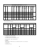
Underhung Geared End Trucks (Refer to Fig. 2-1) Max. Cap. (Tons) Max. Span (ft) End Truck Model # Wheel Flange A B D E* Dia. Range Overall Roller Wheel Beam (in) Std. (in) Length Base Base Beyond (in) (in) (in) Span (in) 2 35 UG-3-0235 4.33 3-6 60 53 39 2 45 UG-3-0245 4.33 3-6 82 75 3 35 UG-3-0335 4.92 3-6 60 53 3 45 UG-3-0345 4.92 3-6 82 5 35 UG-3-0535 5.51 4-6 5 45 UG-3-0545 5.
Underhung Motorized End Trucks (Refer to Fig. 2-1) Max. Max. Cap. Span (Tons) (ft) End Truck Model # Wheel Dia. (in) Flange Range Std. (in) A B D Roller Wheel Length Base Base (in) (in) (in) Overall E* Beam Beyond Span (in) M U ** X Y Width Wheel End Wheel Truck Bottom Beyond Running Frame to Beam Span Surface (in) Width to Top (in) Upper (in) Most Part of ET (in) AA Span to Motor End (in) T/2+11.9 (L/S) 2 35 UML/S/H/D-3-0235 4.33 3-6 60 53 39 12 T+8.1 1.8 11.3-T/2 6.
Max-E-Lift Underhung Geared End Trucks (Refer to Fig. 2-1) E* Beam Beyond Span (in) J Hand Wheel Offset (in) M U ** End Wheel Truck Botto Frame m to Width Beam (in) Top (in) End Y X Truck Wheel Width Beyond Running Weight Surface (lbs/pr) Span to Upper (in) Most Part of ET (in) 66 12 T/2+9.0 T+8.1 1.8 11.3-T/2 6.5 671 92 78 12 T/2+9.0 T+8.1 1.8 11.3-T/2 6.5 746 91 84 66 12 T/2+8.9 T+8.2 1.9 11.3-T/2 6.7 722 3–6 103 96 78 12 T/2+8.9 T+8.2 1.9 11.3-T/2 6.7 797 5.
Max-E-Lift Underhung Motorized End Trucks (Refer to Fig. 2-1) Max. Cap. (Tons) Max. Span (ft) End Truck Model # Whl. Dia. (in) Flange A B Range Overall Roller Std. (in) Length Base (in) (in) 2 35 MUML/S/H/D-3-0235 4.33 3-6 87 80 66 12 T+8.1 2 50 MUML/S/H/D-3-0250 4.33 3–6 99 92 78 12 3 35 MUML/S/H/D-3-0335 4.92 3–6 91 84 66 12 3 50 MUML/S/H/D-3-0350 4.92 3–6 103 96 78 5 35 MUML/S/H/D-3-0535 5.51 4-6 95 88 5 50 MUML/S/H/D-3-0550 5.
2.2 Specifications for Top Running End Trucks AA F A B D E E U Harrington Hoists, Inc. Y X X Figure 2-2 Top Running End Truck Dimensions Top Running Push (Manual) End Trucks (Refer to Fig. 2-2) A Sug. Overall Min. Runway Length (in) Rail (ACSE#) B Roller Base (in) D Wheel Base (in) E Beam Beyond Span (in) U Crane Height Above End Truck (in) X* Width Beyond Span (in) Y Top of Rail to Top of End Truck (in) End Truck Weight (lbs./pr) 61 53 43 2.4 8.4** 4.6 7.1 242 30 98 90 80 2.
Top Running Geared End Trucks (Refer to Fig. 2-2) A Suggested Wheel B D Overall Roller Wheel Min. Diameter Runway Length Base Base (in) (in) Rail (in) (in) (ACSE#) Max. Cap. (Tons) Max. Span (ft) End Truck Model # 1 35 TG-3-0135 3.74 30 61 53 1 50 TG-3-0150 3.74 30 98 3 35 TG-3-0335 6.10 30 3 50 TG-3-0350 6.10 5 35 TG-3-0535 5 50 TG-3-0550 End Y Top of Truck Rail to Weight Top of (lbs.
Top Running Motorized End Trucks (Refer to Fig. 2-2) AA Span to Motor End (in) A Overall Length (in) B Roller Base (in) D Wheel Base (in) 30 61 53 43 2.4 8.4** 4.6 7.1 3.74 30 98 90 80 2.4 8.4** 4.6 7.1 TML/S/H/D-3-0335 6.10 30 62 54 43 4.1 8.4** 4.6 7.1 13.0 (L/S) 60 TML/S/H/D-3-0360 6.10 30 99 91 80 4.1 8.4** 4.6 7.1 13.4 (H) 5 35 TML/S/H/D-3-0535 6.10 40 62 54 43 4.1 8.5 4.7 9.2 14.3 (D) 5 60 TML/S/H/D-3-0560 8.27 40 99 90 74 3.9 8.5 4.
Top Running Motorized End Truck - Gear Motors End Truck Model # Motor Power (Hp) Ea. of Two Travel Speed (FPM) Current (AMPS) Ea. of Two 230V 460V Travel Speed (FPM) Motor Power (Hp) Ea. of Two Current (AMPS) Ea. of Two 230V 460V Travel Speed (FPM) Motor Power (Hp) Ea. of Two Current (AMPS) Ea. of Two 230V Motor End Truck Weight (lbs./ pr) 460V TML/S/H/D-3-0135 40/80 0.33 1.6 1.0 120 0.5 2.1 1.3 80/20 0.33/0.08 1.6/1.1 0.9/0.8 325 TML/S/H/D-3-0160 40/80 0.33 1.6 1.
Max-E-Lift Top Running Motorized End Trucks (Refer to Fig. 2-2) Sug. Min. Wheel Diameter Runway Rail (in) (ASCE#) A Overall Length (in) Max. Cap. (Tons) Max. Span (ft) End Truck Model # 1 35 MTML/S/H/D-3-0135 3.74 30 72 64 54 2.06 36 4.6 7.1 1 60 MTML/S/H/D-3-0160 3.74 30 111 103 93 2.06 36 4.6 7.1 3 35 MTML/S/H/D-3-0335 6.10 30 75 67 56 3.75 36 4.6 7.1 13.0 (L/S) 3 60 MTML/S/H/D-3-0360 6.10 30 112 104 93 3.75 36 4.6 7.1 13.
2.
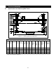
MOTOR GUIDE ROLLERS BRIDGE CONTROL BOX F END TRUCK BRIDGE BEAM GUIDE WIRE BRACES BUMPER SPAN TROLLEY STOP RUNWAY RAIL RAIL SUPPORT STRUCTURE TYPICAL CRANE SYSTEM WITH TOP RUNNING MOTORIZED END TRUCK Figure 2-5 HAND WHEEL GUIDE ROLLERS DRIVE SHAFT END TRUCK F SUPPORT ASSEMBLIES FOR DRIVE SHAFT BRIDGE BEAM GUIDE WIRE BRACES BUMPER SPAN TROLLEY STOP RUNWAY RAIL RAIL SUPPORT STRUCTURE TYPICAL HOIST & TROLLEY HAND CHAIN TYPICAL CRANE SYSTEM WITH TOP RUNNING GEARED END TRUCK Figure 2-6 19
2.4 Bridge Crane Design Requirements - For proper selection of end trucks to meet your particular needs, refer to the Harrington brochure “Choosing the Crane to Fit Your Needs” or our latest catalog. 2.4.1 CRANE RUNWAYS Supporting Structure - Ensure that the supporting structure for the runways is adequate. If necessary consult a professional that is qualified to evaluate the adequacy of the runway's supporting structure.
2.4.2 End Trucks a) Determining Dimensions (1) Underhung - Select the proper runway I-beam from Table 2-2. Be sure runway has enough strength to support the load. Table 2-2 Under Hung Runway I-Beam Dimensions END TRUCK CAPACITY 1 - 3 TON 5 TON I-BEAM FLANGE WIDTH (A) 3” - 6” 4” - 6” MINIMUM HEIGHT OF I-BEAM (B) 6” 8” (2) Top Running - Select the proper rail size from Table 2-3. Be sure runway has enough strength to support the load. Table 2-3 Recommended A.S.C.E.
Improper design or fabrication of crane bridge beam assemblies could result in death or serious injury, and property damage. a) Determining Dimensions - Select the proper crane bridge based on capacity and span from Table 2-4 for single girder bridge cranes. b) For double girder bridge beams consult factory. Table 2-4 BRIDGE BEAMS - Used for Harrington Crane Packages and Systems Capacity Tons Span ft 1/2 1 2 3 5 8 10 10 S8x18.4 S8x18.4 S10x25.4 S12x31.8 S12x40.
This Page Intentionally Left Blank 23
3.0 Assembly, Installation and Trial Operation Installing a crane system on runways supported by inadequate supporting structure could result in death or serious injury, and property damage. Improper design, fabrication, or installation of crane runways could result in death or serious injury, and property damage. All operations associated with the assembly and installation of the crane system should be perfomed under the supervision of qualified personnel. 3.
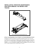
RUNWAYBEAM BRIDGEBEAM TEMPSUPPORT Figure 3-2 3.1.3 Install the remaining frames on the crane bridge and install the end brackets on both ends of the end trucks (See Figure 3-3). Install pinion shafts, pinions, and collars (See Figure 3-3). Geared and motorized only. Runway Beam End Truck Frames A & B Bridge Beam End Bracket Pillow Blocks Pinions & Collars Figure 5 & 6 Figure 3-3 3.1.4 With the temporary support method of 3.1.
A X Y Right Angle B MEASURE DIAGONAL DISTANCES BETWEEN END TRUCK FRAMES. "X" MUST EQUAL "Y" Figure 3-4 3.1.6 Remove the temporary support method of 3.1.2 above. Move the crane along the full length of the runway. Check for binding and guide roller clearance (normal clearance is 3/16 inch from each guide roller to runway beam flange edge). 3.1.7 Install braces on the crane bridge and end trucks. Refer to Figure 3-5. Note: Figure 3-5 depicts a crane with two braces per end truck.
Crane Runway End Truck Bridge Beam Figure 3-6 3.2.3 Refer to Figure 3-7 and check the following. a) Bridge beam centered on each end truck. b) Squareness of end truck frames to bridge beam; (X = Y). Y X Right Angle D MEASURE DIAGONAL DISTANCES BETWEEN END TRUCK FRAMES. "X" MUST EQUAL "Y" Figure 3-7 Make adjustments as necessary. Then securely tighten each fastened connection of the end truck frame to bridge beam. Refer to tightening torque values of Table 3-1. 3.2.
Brace End Truck Bridge Beam Brace Figure 3-8 Another way is to install your crane system is to first assemble the crane on the floor beneath the runway/rails. Then lift the crane into position as shown in Figure 3-9. Travel Rail Figure 3-9 When installing the hoist and trolley on the bridge beam, refer to the installation instructions for your hoist and trolley. 3.3 Max-E-Lift End Trucks (for Double Girder Crane Systems) 3.3.
b) Bridge Beams/Rails Alignment - Ensure that the bridge beams/rails conform to the manufacturer's requirements for the trolley/hoist (e.g. Parallelism, squareness, rail size, clearances, and gauge). c) Bridge Beam Coupling to the End Truck - Ensure that the bridge beams are located on the end trucks so that the center of gravity of the load is transferred to the middle of each end truck. Verify that C1 = C2.
Support Arm 4.9 to 9.8 meters 9.
3.4.2 Single Piece Drive Shaft a) Install the Hand Wheel section of the Drive Shaft first. (1) Slide the Hand Wheel over the Hand Wheel End of the Drive Shaft (the Hand Wheel end of the Drive Shaft is the end with a through-bolt hole two inches from the shaft end). (2) Refer to Figure 3-13 or Figure 3-14 whichever applies and insert the connecting shafts into both ends of the Drive Shaft.
(1) Slide the Hand Wheel over the Hand Wheel End of the Drive Shaft (the Hand Wheel end of the Drive Shaft is the end with a through-bolt hole two inches from the shaft end). (2) Refer to Figure 3-13 or Figure 3-14 whichever applies and insert the Connecting Shaft into the Hand Wheel end of the Drive Shaft. Line up the three holes - hole in the hub of the Hand Wheel, hole in the Drive Shaft and the hole in the Connecting Shaft. Insert the long Bolt B and fasten using the nut and split pin.
(3) Refer to Figure 3-15, and connect the remaining end of the Drive Shaft to the Joint Shaft previously installed at the Bearing Support Assembly and fasten. (4) Slide out the Connecting Shaft from the end of the Drive Shaft nearest the end truck until the through-bolt holes line up between the Connecting Shaft and Drive Shaft. Fasten the Drive Shaft to the Connecting Shaft using Bolt A, slotted nut and split pin.
3.6 Power Source For crane systems requiring electrical power, ALWAYS provide crane runways with Class 3 grounding. Failure to provide an electrical ground in accordance with industry standards and local codes could result in electric shock. NEVER paint any wheels or wheel running surfaces in order to ground the crane properly. Provide electrical power to the crane and any powered components in accordance with applicable industry standards, local codes, and manufacturer's requirements.
3.7 Testing 3.7.1 Record the hoist’s Code, Lot, and Serial Number (from the nameplate on the hoist; see section 9) in the space provided on the cover of this manual. 3.7.2 Prior to initial use the crane system (including all components) should be tested in accordance with the manufacturer's requirements and applicable ANSI standards. ANSI Standards that may apply for crane system applications include: • ANSI B30.2 Overhead and Gantry Cranes • ANSI B30.11 Monorails and Underhung Cranes • ANSI B30.
4.0 Operation For systems using the equipment covered by this manual, the supplier and the owner of the system are responsible for providing information for use by operators for the safe operation of the system. The Crane Manufacturer's Association of America publishes a Crane Operator's Manual that can be useful in properly operating your crane.
5.0 Inspection 5.1 General 5.1.1 The equipment covered by this owner's manual is most commonly used in the design and manufacture of overhead cranes and monorails. The inspection procedure herein is for these applications and is based on the applicable ANSI/ASME B30 volumes, namely: ANSI B30.2 Overhead and Gantry Cranes ANSI B30.11 Monorails and Underhung Cranes ANSI B30.16 Overhead Hoists (Underhung) ANSI B30.
5.2.3 5.2.4 5.3 FREQUENT Inspection - visual examinations by the operator or other designated personnel with intervals per the following criteria: Normal service - monthly Heavy service - weekly to monthly Severe service - daily to weekly Special or infrequent service - as recommended by a qualified person before and after each occurrence.
Table 5-2 Periodic Inspection Requirements of frequent inspection. Deformed, cracked on corroded members Loose or missing bolts, nuts, pins, or rivets. Worn, cracked, or distorted parts such as pins, bearings, wheels, shafts, gears, rollers, locking and clamping devices, bumpers, and stops. Excessive wear of brake system parts Deterioration of electrical components such as controllers, switches, contacts, pushbuttons.
Table 5-3 Inspections Methods and Criteria Crane Component Crane Electric Parts Item Criteria Action 1. Power supply (For cable power supply system) Guide (messenger) wire tension Check visually. The wire must be sufficiently tight to minimize sag. Tighten when necessary. Cable hanger installation and mobility Check visually. The cable must be hung from cable hangers at even intervals. The cable must be hung from the cable hangers so that it does not twist. Replace hangers when necessary.
Table 5-3 Inspections Methods and Criteria Crane Component End Truck Item Method Criteria Action 6. End truck Track wheel (Underhung End Trucks) Measure. Diameter must not be less than "when worn" value in Table 5-4. And, for geared and motorized end trucks the diameter of the drive wheels on the left end truck must not be different from the diameter of the drive wheels on the right end truck by more than the value in Table 5-5. Replace.
Table 5-4 End Truck Wheel Dimensional Data Underhung Crane Std. D Discard Std. t Discard 110 mm 125 mm 140 mm 4.33 inch 4.92 inch 5.51 inch 105 mm 119 mm 133 mm 4.13 inch 4.69 inch 5.24 inch 18 mm 18.5 mm 19 mm 0.71 inch 0.73 inch 0.75 inch 13 mm 13.5 mm 14.5 mm 0.51 inch 0.53 inch 0.57 inch 95 mm 155 mm 3.74 inch 6.10 inch Top Running Crane Std. D Discard Std. D Discard 90 mm 147 mm 3.54 inch 5.79 inch 210 mm 250 mm 8.27 inch 9.84 inch 200 mm 238 mm 7.87 inch 9.
Table 5-7 Motor Brake Discard Limit Applicable Motor Output HP (kW) ØD (in./mm) 0.33 (0.25) 0.5 (0.4) 1.0 (0.75) 2.0 (1.5) T (in./mm) Standard Discard 3.15 (80) 0.43 (11) 0.35 (9) 4.0 (102) 0.51 (13) 0.
6.0 Lubrication Lubricants to be used for the maintenance of your end trucks are listed in the following table. Table 6-1 Table of Approved Lubricants Location Manufacturer and type Amount kW Reduction gear Shell/Albania Grease 2 grams (ounces) Brake disk spline sliding parts of armature Sumitomo Kogyou/Morispeed Grease No. 2 Light coat 44 0.25 0.4 0.75 & 1.5 50 60 150 (1.8) (2.1) (5.
7.0 Maintenance and Handling 7.1 General Components of your End Trucks that require maintenance are as follows: For Motorized End Trucks: Reduction Gearing in the Gear motor Brake Assembly in the Gear motor End Truck Drive Gears For Geared End Trucks: End Truck Drive Gears For Manual End Trucks: 7.2 No items that require maintenance Gear Motor - Reduction Gears a) The reduction gearing in the gear motor should be cleaned and lubricated at least once per year for normal usage.
c) Reassemble as follows: (1) During re-assembly be careful not to pinch the lead wires when assembling the electromagnetic coil 5610. (2) Assemble the motor with the brake disc 512 and armature 513. Ensure that the brake disk is properly oriented and not backwards when installing. (Flat side facing AWAY from motor) (3) Insert the Spring Holder 605 and the Brake Spring 606 into the center recess of the Electromagnetic Coil Assembly 5610.
Brake Adjustment With this gear motor, brake torque can be adjusted within the range of 0 to 50% against the motor rated torque, with the adjusting bolt. Readjust the brake torque when the braking surface of the disk is worn and the braking force decreases. Always set the brake torque for the left and right end trucks at the same value. a) To adjust brake torque refer to Figure 7-2, Table 7-2, and Table 7-3: (1) Loosen the lock nut 604.
Table 7-3 Metric to Imperial Conversion Reference for "H" Values 7.5 17 mm 15 mm 13 mm 11 mm 9 mm 7 mm 0.67” 0.59” 0.51” 0.43” 0.35” 0.28” Storage 7.5.1 Whenever the end trucks are to be placed into storage, place extra grease onto all exposed unpainted parts such as the wheels, gears, collars and splines. Make certain that no debris, dirt or moisture is allowed to accumulate on the end truck during preparations for storage. The storage location should be clean and dry. 7.
8.0 Troubleshooting HAZARDOUS VOLTAGES ARE PRESENT IN THE MOTORIZED END TRUCK AND IN CONNECTIONS BETWEEN COMPONENTS. Before performing ANY maintenance on the equipment, de-energize the electrical supply to the equipment, and lock and tag the supply device in the de-energized position. Refer to ANSI Z244.1, “Personnel Protection - Lockout/Tagout of Energy Sources.” Only Trained and competent personnel should inspect and repair this equipment.
Table 8-1 Troubleshooting Guide Trouble Cause Remedy The rectifier is damaged. Replace the rectifier. The crane is not properly grounded. Ground parts where necessary. The travel surface on the bridge beam or runway is coated with oil, grease, paint, or corrosion. Remove foreign material from travel surface or add ground conductor for hoist power. Water or foreign matter has penetrated the electric parts. Dry parts and remove any foreign matter where necessary.
This Page Intentionally Left Blank 51
9.0 Warranty All products sold by Harrington Hoists, Inc.
10.0 Replacement Par ts Guide When ordering Parts, please provide the Hoist code number, lot number and serial number located on the Hoist nameplate (see Figure 9-1 below). Reminder: Per Sections 1.1 and 3.7.1 to aid in ordering parts and product support, record the hoist Code, Lot and Serial Number in the space provided on the cover of this manual. Figure 9-1 End Truck Nameplate The parts list is arranged into the following sections: Section Page 10.1 Underhung End Trucks................................
Section 10 Replacement Parts 10.
Applicable End Truck Figure No.
Section 10 Replacement Parts 10.
Figure No.
Figure 10-3 Top Running Push End Truck Parts View Section 10 Replacement Parts 10.
Applicable End Truck 59 Figure No.
Figure 10-4 Top Running Motorized End Truck Parts View Section 10 Replacement Parts 10.
Figure No.
Figure 10-5 Top Running Motorized End Truck Parts View Section 10 Replacement Parts 10.
Applicable End Truck 63 Figure No.
Section 10 Replacement Parts 10.
Qty. Per Pair of End Trucks Fig.
Qty. Per Pair of End Trucks Fig. Drawing Number 27 90934-33 28 90125-15 29 90933-76 30 90127-13 31 90435-14 32 HCCF005 * See note A, B, C, and D. ** See note E and F. Name Nut (M12x1.75) Washer (M12) Bolt (M12x60) Spring Washer (M12) “I” Tapered Washer (9º) (M12) Hand Chain Kit A Kit B Kit C Kit D -----1 Pc. 8 4 4 4 4 1 Pc. 16 8 8 8 8 1 Pc. 24 12 12 12 12 1 Pc. Note: 66 A. Use with the following end truck models: UG-3-0235 B.
This Page Intentionally Left Blank
Section 10 Replacement Parts 10.
Fig. No. 1 2 3 4 5 6 Part Name Pinion Top Running Bottom Running Ball Bearing Gear Box “A” Snap Ring Collar “A” *G1 Motor Version Gear 2 *G1 Motor Version Qty. Per Motor 1 1 2 1 1 1 1 *G1D Motor Version 69 7 8 9 10 Snap Ring Gear Box Packing Gear Box “B” Stator Assembly 1 1 1 1 *G1 Motor Version 11 Rotor Assembly *G1D Motor Version 0.
Fig. No. Part Name Qty. Per Motor 21 22 23 24 25 Brake Bracket Terminal Cover Cable Holder Cable Packing Terminal Cover Packing 1 1 1 1 1 26 Bolt [x] 27 Spring Washer [x] 28 29 Snap Ring Screw w/ Spring Washer 1 4 30 Screw w/ Spring Washer [x] 70 G1 Version 31 Ball Bearing 1 G1D Version Bolt [x] 33 34 35 36 Spring Pin Spring Pin Bolt Spring Washer 2 2 8 4 37 Bolt 4 38 40 Screw 7P Terminal Strip 3 [x] 0.5 Hp 120 FPM N6GJ025609 N6GJ3025701S Applicable End Truck 0.33/0.1 Hp 0.
This Page Intentionally Left Blank
Section 10 Replacement Parts 10.
Fig. No. 1 2 3 4 5 6 7 73 8 9 10 11 12 13 14 15 Part Name Pinion Ball Bearing Gear Box “A” Snap Ring Collar “A” Collar “B” *G1 Motor Version *G1 Motor Gear 4 Version *G1D Motor Version Snap Ring Gear Box Packing Gear Box “B” *G1 Motor Version *G1 Motor Gear 2 Version *G1D Motor Version Ball Bearing Stator Assembly *G1 Motor Version Rotor Assembly *G1D Motor Version G1 Motor Version Ball Bearing G1D Motor Version Qty.
Fig. No. 16 17 18 Part Name Qty.
This Page Intentionally Left Blank
Section 10 Replacement Parts 10.
Fig. No. 113A 114 115 116 117 118 119 Qty. Parts per Pair of End Trucks 77 Gear Head Assembly Pinion Axle “G” Collar Axle Holder Snap Ring Snap Ring Ball Bearing 2 2 2 2 2 2 4 153 Drawing/ Part No. N6GO310V5303 N6GO310V301 N6GO310306 N6GO310303 90472-42 90471-20 90005-04 90933-27 90933-28 Bolt 8 154 90127-11 Spring Washer 8 Name Notes 6004-ZZ M8x20 UG-03XX M8x25 TG-01xx thru 0535 M8 A p pl i c a bl e E n d Tr u ck M o d el s: U G- 3- 0 5 x x & TG- 3- 0 5 5 0 Fig. No.
NOTES 78
NOTES 79
www.harringtonhoists.com Harrington Hoists, Inc. 401 West End Avenue Manheim, PA 17545-1703 Phone: 717-665-2000 Toll Free: 800-233-3010 Fax: 717-665-2861 Harrington Hoists – Western Division 2341 Pomona Rd.