
User guide

45
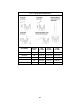
Table 5-5 Hoist (and Trolley) Inspection Methods and Criteria (continued)
Item Method Criteria Action
Wire Rope -
Twisting
Visual
Run the hoist into the highest and lowest
hook positions without load.
If any twisting is detected , untwist the rope
immediately. See Section 6.6 “Reeving and
Adjustments” and Section 6.5 “Wire Rope
Removal”
Inspect the condition of the rope (especially
near pulleys and rope anchorage. See Table
5-5 “Wire Rope- Condition”, “Wire Rope –
Diameter”, “Wire Rope-Broken Wires or
Strands”)
Replace as
required.
Wire Rope -
Lubrication
Visual The wire rope must be maintained in a clean and
well lubricated condition.
Clean/lubricate
(see Section 6.2).
Trolley Side Plates Visual Must be free of significant deformation Replace
Trolley Wheel –
Condition
Visual Trolley Wheel should be free of significant wear,
cracks, nicks and gouges.
Replace.
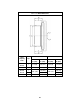
Trolley Wheel –
Tread
Visual, Measure The diameter and width of the tread surface
should not be less than the values listed in Table
5-10. The diameter should not be less than 5% of
its original diameter as new.
Replace.
Trolley Wheel –
Gear
Visual Teeth should not be cracked, damaged, or
excessively worn.
Replace.
Load Bar Visual, Measure Load Bar should be free of significant wear,
cracks, nicks and gouges. Load Bar should not
be bent.
Replace.
Trolley Motor
Brake
Visual Braking action should not be overly abrupt and
should not allow excessive drift. The brake disc
(brake rotor) should not exceed the maximum
permissible air gap (S) values listed in Table 5-
11.
Replace.
Contactor
Contacts
Visual Contacts should be free of significant pitting or
deterioration.
Replace.
Sheaves Visual Sheave should be free of significant wear. The
wall thickness, t, should not be less than the “t
min” values in Table 5-9. The groove depth, h,
should not be greater than the “h max” values
listed in Table 5-9. They should also be checked
for easy running, indicating that the ball bearings
are in good condition.
Replace.
Pendant –
Switches
Function Depressing and releasing push buttons should
make and break contacts in switch contact block
and result in corresponding electrical continuity or
open circuit. Push buttons should be interlocked
either mechanically or electrically to prevent
simultaneous energizing of circuits for opposing
motions (e.g. up and down, forward and reverse).
Repair or replace
as necessary.