EFFECTIVE: December 20, 2012 ELECTRIC WIRE ROPE HOIST and TROLLEY RHN SERIES 2 Ton through 20 Ton Capacity Hoist Code and Serial Number This equipment should not be installed, operated or maintained by any person who has not read and understood all the contents of this manual. Failure to read and comply with the contents of this manual can result in serious bodily injury or death, and/or property damage.
Table of Contents Section 1.0 2.0 3.0 4.0 5.0 Page Number Important Information and Warnings…………………………………………….……………………. 4 1.1 Terms and Summary 1.2 Warning Tags and Labels Technical Information …………………………….…………………………………………………….. 8 2.1 Specifications 2.2 Dimensions 2.3 Miscellaneous Pre-operational Procedures……………………………………………………………………….….. 20 3.1 General Information 3.2 Handling 3.3 Mounting Location 3.4 Assembly, Adjustments and Mounting 3.5 Electrical Connections 3.
Section 5.7 6.0 Page Number Inspection Methods and Criteria Maintenance & Handling………………………………………………………………………….…… 52 6.1 Count/Hour Meter 6.2 Lubrication 6.3 Hoist Motor Brake 6.4 Trolley Motor Brake 6.5 Wire Rope 6.6 Reeving and Anchorage 6.7 Storage 6.8 Outdoor Installation 6.9 Optional Environment 7.0 Troubleshooting………………………………………………………………………………………… 65 8.0 Warranty…………………………………………………………………………………………………. 69 9.0 Parts List ……………………………………………………………………………………………….
1.0 Important Information and Warnings 1.1 Terms and Summary This manual provides important information for personnel involved with the installation, operation and maintenance of this product. Although you may be familiar with this or similar equipment, it is strongly recommended that you read this manual before installing, operating or maintaining the product. Danger, Warning, Caution and Notice - Throughout this manual there are steps and procedures that can present hazardous situations.
Equipment described herein is not designed for and MUST NOT be used for lifting, supporting, or transporting people, or for lifting or supporting loads over people. Equipment described herein should not be used in conjunction with other equipment unless necessary and/or required safety devices applicable to the system, crane, or application are installed by the system designer, system manufacturer, crane manufacturer, installer, or user.
HAZARDOUS VOLTAGES ARE PRESENT IN THE CONTROL BOX, OTHER ELECTRICAL COMPONENTS, AND CONNECTIONS BETWEEN THESE COMPONENTS. Before performing ANY mechanical or electrical maintenance on the equipment, de-energize (disconnect) the main switch supplying power to the equipment; and lock and tag the main switch in the de-energized position. Refer to ANSI Z244.1, “Personnel Protection – Lockout/Tagout of Energy Sources”. Only trained and competent personnel should inspect and repair this equipment.
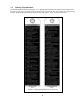
1.2 Warning Tag and Labels The warning tag illustrated below in Figure 1-1 is supplied with each RHN hoist and trolley hoist shipped from the factory. If the tag is not attached to the pendant cord for your hoist/trolley, order a tag from your dealer and install it. Read and obey all warnings attached to this Trolley Hoist. Tag is not shown actual size.
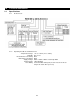
2.0 Technical Information 2.1 Specifications 2.1.1 Product Code: 2.1.
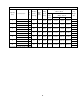
Table 2-1 Deck Mounted Hoist Specifications Dual Speed Hoist Lifting Motor Capacity (Ton) Product Code* RHN02D-20A-20D- Lift (ft.) Reeving (Parts/ reeving) 3 Phase, 60 Hz Lifting Speed Output Current Draw Net Weight (ft/min) (Hp) (amps) - Hi/Low (lbs) Hi/Low 208&230V 460V 575V 5.8/0.9 17.0/8.4 8.3/4.0 6.6/3.
Table 2-2 Ultra-Low Headroom Trolley Hoists Hoist Specifications Dual Speed Hoist Lifting Motor Capacity (Ton) Product Code* RHN02U-20A-20DD- Lift (ft.) Reeving (Parts/ reeving) Output Current Draw Net Weight (ft/min) (Hp) (amps) - Hi/Low (lbs) Hi/Low 208&230V 460V 575V 5.8/0.9 17.0/8.4 8.3/4.0 6.6/3.2 617 4/1 RHN02U-33A-20DD- 33 RHN03U-20A-20DD- 20 3 RHN03U-33A-20DD- 33 RHN05U-20B-20DD- 20 5 33 RHN08U-20C-20DD- 20 7½ 20/3.5 617 7 20/3.5 5.8/0.9 17.0/8.4 8.3/4.
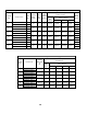
2.2 Dimensions Figure 2-1 2-10 ton Deck Mounted Hoist Figure 2-2 15-20 ton Deck Mounted Hoist Dimensions (See Table 2-4) Dimensions (See Table 2-5) Table 2-4 Deck Mounted Hoist Dimensions (2-10 ton)** Capacity (Tons) Min. Headroom Product Code* C (in) RHN02D-20A-20D- 2 e1 e2 e3 e4 e5 e6 e7 e9 e10 e11 e13 e14 e15 e16 eA (in) (in) (in) (in) (in) (in) (in) (in) (in) (in) (in) (in) (in) (in) (in) 6.3 4.6 9.0 4.8 13.9 21.3 11.5 4.9 7.2 6.3 11.0 40.9 22.
Table 2-6 Ultra-Low Headroom Trolley Hoist Dimensions Capacity (Tons) e1 e4 e10 d1 d2 d3 f1 f2 f3 f5 f6 u1 u2 u3 u4 u5 u6 (in) (in) (in) (in) (in) (in) (in) (in) (in) (in) (in) (in) (in) (in) (in) (in) (in) RHN02U-20A-20DD- 40.3 4.6 11.9 30.0 22.4 9.1 11.5 28.6 18.0 3.7 13.9 8.9 6.5 6.1 5.1 5.9 RHN02U-33A-20DD- 51.9 7.6 10.7 41.6 34.1 9.0 RHN03U-20A-20DD- 40.3 4.6 11.9 30.0 22.4 9.1 Product Code *1 2 3 11.5 28.6 18.0 3.
Table 2-7 Ultra-Low Headroom Trolley Motor Dimensions Capacity (Tons) m0 (in) Product Code* RHN02U-20A-20DD- 20.6 RHN02U-33A-20DD- RHN03U-20A-20DD- 3 20.6 RHN03U-33A-20DD- RHN05U-20B-20DD- 5 20.6 RHN05U-33B-20DD- RHN08U-20C-20DD- 7½ 22.4 RHN08U-33C-20DD- RHN10U-20C-20DD- 10 22.4 RHN10U-33C-20DD- RHN15U-28D-12DD- 15 26.5 RHN15U-46D-12DD- *See Section 2.1.1 for place holder designation 2 m1 (in) m2 (in) 7.4 1.3 7.4 1.3 7.4 1.3 9.5 0.8 9.5 0.8 10.1 1.
2.3 Miscellaneous Table 2-9 Hook Dimension* Units = inch Capacity (Tons) Product Code** a b c d e f g h 2.2 1.8 1.9 1.5 2.2 2.5 1.6 5.8 2.2 1.8 1.9 1.5 2.2 2.5 1.6 5.8 2.6 2.1 2.3 1.8 2.5 2.8 1.7 6.6 3.1 2.5 2.6 2.1 2.8 3.1 1.9 7.7 3.1 2.5 2.6 2.1 2.8 3.1 1.9 7.7 3.9 3.1 3.3 2.6 3.5 4.0 2.4 10.1 4.9 3.9 4.2 3.3 4.4 5.0 3.2 12.0 4.9 3.9 4.2 3.3 4.4 5.0 3.2 12.
Table 2-10 Deck Mounted Hoist Attachment Point Dimensions (2-10 ton) Capacity (Tons) Product Code* e1 (in) e12 (in) RHN02D-20A-20D- 40.9 24.2 RHN02D-33A-20D- 52.5 35.8 RHN03D-20A-20D- 40.9 24.2 RHN03D-33A-20D- 52.5 35.8 RHN05D-20B-20D- 41.3 24.2 RHN05D-33B-20D- 52.9 35.8 RHN08D-20C-20D- 48.0 26.8 RHN08D-33C-20D- 60.4 39.2 RHN10D-20C-20D- 48.0 26.8 RHN10D-33C-20D- 60.4 39.2 Deck/Base Mounted 2 3 5 7 1/2 10 Notes: *See Section 2.1.
Table 2-11 Deck Mounted Hoist Attachment Point Dimensions (15 & 20 ton) Capacity (Tons) Product Code* e1 (in) RHN15D-20D-16D- 54.4 15 e2 (in) e12 (in) Deck/Base Mounted 33.7 43.7 RHN15D-33D-16D- 66.6 45.9 RHN20D-20D-16D- 54.4 33.7 20 43.7 RHN20D-33D-16D- 66.6 45.9 Notes: *See Section 2.1.
Table 2-12 Reaction Forces at Rated Load, Deck Mounted Capacity (Tons) 2 3 5 7½ 10 15 20 Product Code F1 (lbs) F2 (lbs) F3 (lbs) F4 (lbs) Q1 (lbs) Q2 (lbs) Q3 (lbs) Q4 (lbs) RHN02D-20A-20D- RHN02D-33A-20D- RHN03D-20A-20D- RHN03D-33A-20D- RHN05D-20B-20D- RHN05D-33B-20D- RHN08D-20C-20D- RHN08D-33C-20D- RHN10D-20C-20D- RHN10D-33C-20D- RHN15D-20D-16D- RHN15D-33D-16D- RHN20D-20D-16D- RHN20D-33D-16D- 1817 1950 2700 2906 4171 4480 6989 7758 9041 10042 9297 10384 12088 13494 1902 2149 3043
Table 2-13 Wheel Pair Reaction Forces at Rated Load, Ultra-Low Headroom Monorail Trolley Capacity (Tons) 2 3 5 7 1/2 10 15 Product Code* R1 (lbs) R2 (lbs) RHN02U-20A-20DD- 2985 2939 RHN02U-33A-20DD- 3632 2411 RHN03U-20A-20DD- 4292 4285 RHN03U-33A-20DD- 5253 3487 RHN05U-20B-20DD- 6629 7288 RHN05U-33B-20DD- 7167 6675 RHN08D-20C-20DD- 9102 12320 RHN08U-33C-20DD- 12011 9860 RHN10U-20C-20DD- 11783 16192 RHN10U-33C-20DD- 15641 12898 RHN15U-28D-12DD- 22045 17881
Table 2-14 Trolley Wheel Dimensions Capacity (Tons) Product Code *5 Wheel Dia. w1 w2 w3 w4 w5 w6 w7 w8 w9 ∅D (in) (in) (in) (in) (in) (in) (in) (in) (in) *2 U (ft) (in) 2 3 5 7 1/2 10 15 RHN02U-20A-20DD- RHN02U-33A-20DD- RHN03U-20A-20DD- RHN03U-33A-20DD- RHN05U-20B-20DD- RHN05U-33B-20DD- RHN08D-20C-20DD- RHN08U-33C-20DD- RHN10U-20C-20DD- RHN10U-33C-20DD- RHN15U-28D-12DD- RHN15U-46D-12DD- Maximum Flange Thickness t (in) 3.1 1.6 4.1 1.2 1.1 0.5 (0.6)** 0.2 2.
3.0 Pre-operational Procedures 3.1 General Information 3.1.1 When the RHN trolley hoist or deck mounted hoist is incorporated into lifting systems utilizing other equipment, follow and complete all pre-operational procedures and instructions provided with the equipment. Special wiring considerations must also be taken to complete the integration of the RHN trolley hoist or deck mounted hoist into the system. 3.1.2 The RHN hoist is delivered pre-assembled on a pallet with a wooden frame.
Figure 3-2 Lift Point for Deck Mount 3.3 Figure 3-3 Lift Point for Trolley Hoist Mounting Location 3.3.1 Prior to mounting the RHN deck mounted hoist, ensure that the substructure is adequate and capable of withstanding the forces generated by the hoist and the load. Therefore, the substructure must be torsion resistant and level (See Table 2-12 for more details).
3.4 Assembly, Adjustments and Mounting When installing the trolley hoist on a beam, ALWAYS raise the hoist into position with the trolley assembled together and securely attached to a pallet. Raise the trolley hoist with a forklift, lifting platform, or other similar means. NEVER use slings to raise and install the trolley hoist onto the beam (see Figure 3-4).
b. With the nuts (2) loosened enough to allow the trolley frame to move, slide the trolley motor side of the hoist outward or inward to meet the desired flange width. Tighten nuts (2) with a torque wrench, to 155 ft lbs (210 Nm). (See Figure 3-6 and Figure 3-11.) 7) Installing the Drive Shaft a. 2Ton – 10Ton Trolley Hoist Install Snap Rings (S) on to Driveshaft (D) in position X3 or X4 depending on flange width (B) of the runway beam and length (L) of drive shaft (D).
Figure 3-4 Lift Point for Deck Mount Figure 3-5 Lift Point for Trolley Hoist Figure 3-6 Trolley Hoist Clearances 2 Ton – 10 Ton Figure 3-7 Trolley Hoist Clearances Table 3-1 Trolley Clearances and Wheel Diameters Hoist RHN02 RHN03 RHN05 RHN08 RHN10 RHN15 Wheel Diameter c f/2 y in mm in mm in mm in mm 3 1/8 80 B+2 5/8 B+67 1/16 1.5 5 3/8 137 4 100 B+2 5/8 B+67 1/16 1.5 5 3/4 147 5 1/2 140 B+2 5/8 B+67 1/16 1.5 6 3/8 162 8 200 B+3 5/8 B+67 1/16 1.
Figure 3-8 Hoist RHN02 RHN03 RHN05 RHN08 RHN10 RHN15 Figure 3-9 Table 3-2 Drive Shaft Length and Positions for Fig 3-8, 3-9 and 3-11 Drive Shaft Beam Flange Width Shaft Length Snap Ring in. (mm) “L” (mm) Position “S” 3.25-5.71 (82-145) X3 15.35 (390) 5.75-7.68 (146-195) X4 7.72-9.84 (196-250) X3 19.49 (495) 9.88-12.05 (251-306) X4 12.09-13.78 (307-350) X3 23.43 (595) 13.82-15.71 (351-399) X4 15.75-17.72 (400-450) X3 27.36 (695) 17.76-19.69 (451-500) X4 3.63-5.71 (92-145) X3 15.35 (390) 5.75-7.
Table 3-3 L3 and L4 Dimensions from Fig 3-8 and 3-9 Hoist L3+/- 2 in. (mm) L4+/-2 in. (mm) RHN02, RHN03, 3.8 (96.4) 1.82 (46.4) RHN05 RHN08, RHN10 4.9 (124.6) 1.82 (46.
3.5 Electrical Connections 3.5.1 3.5.2 3.5.3 3.5.4 Ensure that the voltage of the electric power supply is proper for the trolley hoist. Do NOT apply electronic soft-start control or voltage varying controls to the RHN lifting or traversing motors. Use of such devices may cause the motor brake and other electrical components to malfunction. For variable frequency drives contact Harrington for more information.
3.6 Pendant Installation 1) Refer to Figure 3-14, Figure 3-15 and the wiring diagram and the interconnection diagram provided with the Hoist. 2) Remove Control Cover. 3) Loosen the cable fitting located on the lower side of the electrical enclosure and insert the Pendant Cable. Pull through enough cable to reach the terminals then securely tighten the cable fitting. 4) Attach a strain relief cable or chain between the pendant and hoist.
3.7 RPU Load Monitor Device The RHN hoist is equipped with the RPU Load Monitor Device. The RPU version (SLE21 or SLE22) is located on the front cover of the RPU unit. The main function of this device is to evaluate the load conditions of the hoist (overload protection, temperature monitoring of the hoist and trolley motors, and displaying the operating hours of the hoist. 3.7.
Figure 3-16 3.8 Hoist Limit Switches and Adjustment The RHN wire rope hoist is equipped with a geared limit switch in the hoist control panel box. The limit switch is equipped with four switches, all of which are utilized for standard hoist functions. The four limit switch positions are as follows: S1 (Upper Safety Limit), S2 (Lower Limit), S3 (Upper Limit), and S4 (Speed Transition Limit). The wire rope hoist is also equipped with a BLS (Block Limit Switch) as a standard feature. 3.8.
S4 ↓ ↓ location and the switch on the geared limit is no long activated. The hoist high speed function is now enabled and will function if high speed if desired by the operator. S2 ↓ (Lower Geared Limit): When the S2 ↓ switch position is activated, hook travel is disabled in the down direction.
3) The upper geared limit switch S3 ↑ should activate before the BLS ↑ limit switch. If this is not the case, reset the S3 ↑ limit switch according to Section 3.8.7 4) Observe that the distance between the top of the hook block and the next obstacle is greater than 3.5”. This distance is the minimum clearance dimension (2”) plus the minimum distance between S3 ↑ and BLS ↑ (¾”) plus the minimum distance between BLS ↑ and S1 ↑ (¾”), see Figure 3-17. If the clearance dimension is less than 3.
Turning to the right: switching point is moved “upwards”. 4) Adjusting the gear limit switch All the cam discs can be moved together with the aid of the black setscrew (SO), Figure 3-21. The settings of the individual contacts relative to one another remain unchanged. The gear ratio inside the limit switch is very high and in some instances it might require many revolutions of the set screws to adjust the proper position. Set the limit switch using a screwdriver and without using excessive force.
Lower bottom hook block to desired hook position, if necessary turn setscrew (S2) to the left before hand. Turn setscrew (S2) to the right until contact S2 switched audibly Check disconnect point Figure 3-21 3.8.8 3.9 Servicing limit switch Maintenance work is restricted to checking the cut-off points.
3.9.3 3.9.4 Confirm proper operation: Before operating read and become familiar with Section 4 – Operation. Before operating ensure that the hoist (and trolley) meets the Inspection, Testing and Maintenance requirements of ANSI/ASME B30.16. Before operating ensure that nothing will interfere with the full range of the hoist’s (and trolley’s) operation. Proceed with trial operation to confirm proper operation. Verify that the controls agree with hoist direction.
4.0 Operation 4.1 Introduction DO NOT WALK UNDER A SUSPENDED LOAD HOIST OPERATORS SHALL BE REQUIRED TO READ THE OPERATION SECTION OF THIS MANUAL; THE WARNINGS CONTAINED IN THIS MANUAL, INSTRUCTION AND WARNING LABELS ON THE HOIST OR LIFTING SYSTEM, AND THE OPERATION SECTIONS OF ANSI/ASME B30.16 and ANSI/ASME B30.10. THE OPERATOR SHALL ALSO BE REQUIRED TO BE FAMILIAR WITH THE HOIST AND HOIST CONTROLS BEFORE BEING AUTHORIZED TO OPERATE THE HOIST OR LIFTING SYSTEM.
The operation of an overhead hoist involves more than activating the hoist’s controls. Per the ANSI/ASME B30 standards, the use of an overhead hoist is subject to certain hazards that cannot be mitigated by engineered features, but only by the exercise of intelligence, care, common sense, and experience in anticipating the effects and results of activating the hoist’s controls.
Improper operation of a hoist can create a potentially hazardous situation which, if not avoided, could result in minor or moderate injury, or property damage. To avoid such a potentially hazardous situation, THE OPERATOR SHALL: • Maintain a firm footing or be otherwise secured when operating the hoist. • Use the hoist manufacturer’s recommended parts when repairing the unit. • Check brake function by tensioning the hoist prior to each lift operation.
5.0 Inspection 5.1 General 5.1.1 The inspection procedure herein is based on ANSI/ASME B30.16. The following definitions are from ANSI/ASME B30.16 and pertain to the inspection procedure below. Designated Person – a person selected or assigned by the employer or employer’s representative as being competent to perform the specific duties.
5.2.4 PERIODIC Inspection – visual inspection by a designated person with intervals per the following criteria: Table 5-2 Periodic Inspection Intervals 5.3 Service Hoist and Trolley Interval Normal Service Yearly Heavy Service Semiannually Severe Service Quarterly Special or Infrequent Service As recommended by a qualified person before the first such occurrence and as directed by the qualified person for any subsequent occurrences.
5.4 Periodic Inspection 5.4.1 Inspections should be made on a PERIODIC basis in accordance with Table 5-4, “Periodic Inspection.” A designated person shall make evaluation and resolution of the results of PERIODIC Inspections such that the hoist is maintained in safe working condition. 5.4.2 For inspections where load suspension parts of the hoist/trolley are disassembled, a load test per ANSI/ASME B30.16 must be performed on the hoist/trolley after it is re-assembled and prior to its return to service.
5.6 5.7 Inspection Records 5.6.1 Dated inspection reports and records should be maintained at time intervals corresponding to those that apply for the hoist’s PERIODIC interval per Section 5.2.4. These records should be stored where they are available to personnel involved with the inspection, maintenance, or operation of the hoist/trolley. 5.6.
Table 5-5 Hoist (and Trolley) Inspection Methods and Criteria (continued) Item Method Criteria Action Hook Block – Sheave(s) and Shaft Visual, Function Sheave(s) should be free of significant wear. Sheave surfaces should be free of nicks, gouges, dirt and grime. Bearing parts and surfaces of Sheave and Shaft should not show significant wear. Sheave should rotate freely with no roughness or significant free play. Clean/lubricate, or replace as required.
Table 5-5 Hoist (and Trolley) Inspection Methods and Criteria (continued) Item Method Criteria Action The full length of the Wire Rope must be inspected for rope diameter, broken strands or wires, and condition. The rope must be free of load for testing to detect any broken wires when bending the rope by hand (especially by radius of rope sheeve).
Table 5-5 Hoist (and Trolley) Inspection Methods and Criteria (continued) Item Wire Rope Twisting Method Visual Criteria Run the hoist into the highest and lowest hook positions without load. If any twisting is detected , untwist the rope immediately. See Section 6.6 “Reeving and Adjustments” and Section 6.5 “Wire Rope Removal” Inspect the condition of the rope (especially near pulleys and rope anchorage.
Table 5-5 Hoist (and Trolley) Inspection Methods and Criteria (continued) Item Method Criteria Action Pendant Housing Visual Pendant housing should be free of cracks and mating surfaces of parts should seal without gaps. Replace Pendant - Wiring Visual Wire connections to switches in pendant should not be loose or damaged. Tighten or repair Pendant and Power Cords Visual, Electrical Continuity Surface of cord should be free from nicks, gouges, and abrasions.
Table 5-7 Wire Rope Wear Dimensions Maximum Allowable Number of Broken Wires Rope Diameter Hoist Capacity (tons) Standard Rope Diameter Discard For 6xDia. Length (mm) No. Broken Wires For 30xDia. Length in. (mm) No. Broken Wires in. (mm) 8.27 (210) Length Length (mm) (mm) (in) RHN02(D/U) 7 6.3 0.25 7 13 1.65 (42) 26 RHN03(D/U) 7 6.3 0.25 7 13 1.65 (42) 26 8.27 (210) RHN05(D/U) 9 8.1 0.32 9 13 2.13 (54) 26 10.63 (270) RHN08(D/U) 12.5 11.25 0.44 12.5 13 2.
Table 5-8 - Hoist Motor Brake Hoist Capacity Code Motor Type RHN02(D/U) RHN03(D/U) RHN05(D/U) RHN08(D/U) RHN10(D/U) RHN15U RHN15D RHN20D Dual speed Dual speed Dual speed Dual speed Dual speed Dual speed Dual speed Dual speed S max. in. (mm) .031 (0.8) .031 (0.8) .035 (0.9) .071 (1.8) .071 (1.8) .071 (1.8) .071 (1.8) .071 (1.8) 48 a in. (mm) .98 (25) .98 (25) .98 (25) 1.18 (30) 1.18 (30) 1.18 (30) 1.18 (30) 1.18 (30) Screw Torque ft-lbs (Nm) 6.6 (9) 6.6 (9) 6.
Table 5-9 Rope Sheave Dimensions Part Number Diameter (mm) t min in. (mm) h max in. (mm) h new in. (mm) RHN0032 125 0.16 (4) 0.55 (14) 0.47 (12) RHN0129 160 0.16 (4) 0.75 (19) 0.65 (16.5) RHN0191 225 0.22 (5.5) 0.94 (24) 0.83 (21) RHN0327 250 0.22 (5.5) 1.10 (28) 0.98 (25) RHN0260 375 0.26 (6.5) 1.48 (37.5) 1.
Table 5-10 Wheel Dimensions Nominal value Hoist Capacity Code Fig. RHN02 RHN03 Limit for wear d in. (mm) b in. (mm) d1 in. (mm) b2 in. (mm) 1 3.15 (80) 1.08 (27.5) 2.99 (76) 1.16 (29.5) RHN05 1 3.94 (100) 1.30 (33) 3.74 (95) 1.38 (35) RHN08 RHN10 1 2 RHN15U 2 5.51 (140) 7.87 (200) 1.75 (44.5) 1.67 (42.5) 1.67 (42.5) 50 5.24 (133) 7.48 (190) 1.85 (47) 1.77 (45) 1.
Table 5-11- Travel Motor Brake Hoist Capacity Code RHN02U RHN03U RHN05U RHN08U RHN10U RHN15U Motor Type Motor Speed (fpm) Dual speed Dual speed Dual speed Dual speed Dual speed Dual speed 80/20 80/20 80/20 80/20 80/20 80/20 S min. in. (mm) .008 (0.2) .008 (0.2) .008 (0.2) .008 (0.2) .008 (0.2) .012 (0.3) 51 S max. in. (mm) .079 (2.0) .079 (2.0) .079 (2.0) .063 (1.6) .063 (1.6) .079 (2.0) t in. (mm) .22 (5.7) .22 (5.7) .22 (5.7) .24 (6.1) .24 (6.1) .35 (8.8) Screw Torque ft-lbs (Nm) 2.2 (3) 2.
6.0 Maintenance and Handling 6.1 Hour Meter The RHN Hoist is equipped with a Counter, located on the face of the RPU Load Monitor Device. This counter registers and displays the total operating hours of the hoist (See Figure 6-1). Figure 6-1 Hour Meter 6.2 Lubrication 6.2.1 6.2.2 6.2.3 6.2.4 Wire Rope: For proper performance the Wire Rope must be maintained in a clean and well lubricated condition.
Table 6-1 Lubrication Point a Hoist Gear Box Type of Lubricant Quantity of Lubricant Characteristics, Makes Oil - US quarts (ml) Grease - Ounces (g) RHN02, RHN03 1.7 (1500) RHN05 2.1 (2000) RHN08,RHN10 6.3 (6000) RHN15, RHN20 16.9 (16000) 19 (18000)1 Oil 1 Viscosity: 460 /s/40°C (220/s/40°C), pour point: -20°C (40°C) flash point: +265°C (+320°C), e.g.
6.3 Hoist Motor Brake 6.3.1 To keep your hoist working in optimum condition and prevent possible down time, it is recommended to check your motor brake at regular intervals. Intervals must be adapted in accordance with the application. 6.3.2 Before proceeding, ensure that the electrical supply for the hoist or trolley has been de-energized (disconnected). Lock out and tag out in accordance with ANSI Z244.1 “Personnel Protection –Lockout/Tagout of Energy Sources”.
Figure 6-2 Figure 6-1 55
6.3.5 6.4 Motor Brake Re-assembly – Reassemble the parts in reverse order of removal. Ensure that the check hole for measuring the air gap is underneath. Observe tightening torques in Table 5-8. Trolley Motor Brake 6.4.1 6.4.2 6.4.3 To keep your hoist working in optimum condition and prevent possible down time, it is recommended to check your motor brake at regular intervals. Intervals must be adapted in accordance with the application.
Figure 6-3 6.4.5 6.5 Motor brake reassembly – Reassemble the parts in reverse order of removal. Ensure that the check hole for measuring the air gap is underneath. Observe tightening torques in Table 5-11. Wire Rope 6.5.1 6.5.2 Lubrication and Cleaning – Refer to Section 6-2. Be certain that the replacement wire rope is obtained from Harrington Hoists, Inc. and is the correct wire rope for the hoist. See factory certificate for part number of rope.
6.5.3 After commissioning a new wire rope hoist, or after replacing the rope, the rope of multi-fall hoists may twist. This can be seen from the bottom hook block turning, particularly when unloaded. Twisting in the rope prejudices safety and service life. Remove any twists! Regularly inspect the rope for twisting and follow the procedure in Table 5-5 “Wire Rope-Twisting” and other corresponding Wire Rope sections in Table 5-5. 6.5.
6.5.5 1) Figure 6-5 Fig 6-6 Figure 6-7 Figure 6-8 Wire Rope Installation/Rope Guide Installation The hoist must be properly powered and operational in order to perform the following procedures. 2) 3) When replacing Wire Rope, check for wear on mating parts, i.e. Drum, Sheaves, Hook Block Sheaves, and replace if necessary. ALWAYS unwind the roll of the new Wire Rope without kinks or bends (see Figure 6-9). Protect the rope from dirt.
Figure 6-9 7) Press the “UP” button on the Pendant to wind the Wire Rope onto the Drum. Tightly wind about 5-10 turns onto the drum (see Figure 6-8). Let the rope run through a greased rag. See Section 6.1 for grease type. 8) Without loosening the tension on the Wire Rope, clamp a weight onto the Wire Rope below the Rope Guide, taking care not to damage the Wire Rope. Replacing the manual tension with the weight will prevent the Wire Rope from unrolling off the Drum.
Figure 6-10 Figure 6-11 Figure 6-12 Figure 6-13 Figure 6-14 Figure 6-15 10) Carry out again all the sequences described in Section 6.6 “Reeving and Adjustments”. Lubricate the Wire Rope, the Rope Guide and Drum (see Section 6.2). 11) Retighten clamping plates. Torque the Screws to the value shown in Table 6-1 for your hoist (see Figure 6-8). 12) Run rope in with a partial load.
6.6 Reeving and Anchorage 6.6.1 Reeving the bottom block Use a pliers to hold the rope securely. 1. The hoist must be energized in order to complete the reeving of the rope. Take extreme caution while performing this operation. 2. Lay out the end of the rope that is not wound on the drum. Let this end hang freely. 3. Make certain that the wire rope lies snuggly on the rope drum. Avoid wire rope slack at all times. Slack will cause premature rope guide wear as well wire rope wear. 4.
Figure 6-18 Table 6-2 Anchorage Specifications Rope Clamp Deck Mount Rope Wedge Torque Setting Hoist Projection “x” ft lbs (Nm) RHN02 7.4 (10.0) RHN03 6 mm RHN05 14.8 (20.0) RHN08 29.7 (40.0) 15 mm RHN10 RHN15 70.5 (95.0) Rope Clamp Trolley Rope Wedge Torque Setting Hoist Projection “x” ft lbs (Nm) RHN02 7.4 (10.0) RHN03 6 mm RHN05 14.8 (20.0) RHN08 29.7 (40.0) RHN10 15 mm RHN15 96.5 (130.
Anchorage Configurations (Continued) Table 6-3 RHN02, RHN03,RHN05, RHN08, RHN10 Trolley Hoist “a” and “b” dimensions (mm) Hoist Model RHN02 RHN03 RHN05 a b 216 241 265 290 334 366 RHN08 RHN10 Figure 6-23 RHN15 11. Operate the hoist several times up and down (without a load) for the entire length of the lift. 12. Repeat with increasing loads 13. Inspect for twist while operating the hoist. Severe twist will cause the bottom block to turn.
7.0 Troubleshooting HAZARDOUS VOLTAGES ARE PRESENT IN THE HOIST AND IN CONNECTIONS BETWEEN COMPONENTS. Before performing ANY troubleshooting on the equipment, de-energize the supply of electricity to the equipment, and lock and tag the supply device in the de-energized position. Refer to ANSI Z244.1, “Personnel Protection Lockout/Tagout of Energy Sources.” Only Trained and competent personnel should inspect and repair this equipment.
Table 7-1 Troubleshooting Guide Symptom Hoist lifts but will not lower Cause Remedy Down circuit open Check circuit for loose connections. Check down limit switch for malfunction. Broken conductor in pendant cord Check the continuity for each conductor in the cable. If one is broken, replace entire cable. Faulty magnetic contactors Check coils for open or short circuit. Check all connections on motor circuit. Check for burned contacts. Replace as needed.
Table 7-1 Troubleshooting Guide Symptom Overheating Hoist and/or Trolley operates intermittently Trolley making loud noise. Trolley will not move Abnormal noise from wire rope and/or drum Cause Remedy Wrong voltage or frequency Check voltage and frequency of power supply against the rating on the nameplate on the motor. Brake drags Check motor brake adjustment for proper clearance.
• Check voltage (terminal 6) System error • Switch RPU off/on • Replace RPU • Check voltage (terminal 6) No control voltage, faulty fuse, faulty Load Monitor • Switch RPU off/on • Replace RPU 68
8.0 Warranty All products sold by Harrington Hoists, Inc.
9.0 Parts List When ordering Parts, please provide the Hoist product number and serial number located on the Hoist nameplate (see fig. below). Reminder: Per Sections 1.1 and 3.9.1 to aid in ordering Parts and Product Support, record the Hoist product number and serial number in the space provided on the cover of this manual. The parts list is arranged into the following sections: Section Page 9.1 Hoist Motor Parts ........................................................................................
9.
9.1 Hoist Motor Parts Figure No.
Gearing Parts RHN02, RHN03, RHN05, RHN08, RHN10 10 Figure 9-2-1 Gearing Parts 73
9.2 Gearing Parts Figure No.
9.
9.2 Gearing Parts Figure No. 25 Part Name GEAR BOX ASSEMBLY 1 1 Parts Per Hoist RHN15U 1 RHN0310 RHN15D RHN0312 Gear box 1 RHN0223 2 Gear cap 1 RHN0224 3 Seal 1 RHN0225 4 Socket head cap screw 12 90912124 5 Lock washer 12 9098511 6 Dowel pin 2 RHN0226 7 Gear wheel 1 RHN0227 8 Retainer ring 1 9047192 9 Drive shaft 1 RHN0228 10 Bearing 1 9001223 11 Shaft seal 1 RHN0229 2 12 13 Shim , 110 x 125 x 0.3 mm RHN0230 1 2 Shim , 110 x 125 x 0.
9.
9.3 Rope Drum Parts Figure No. Part Name Parts Per Hoist 1 Rope Drum – 20 ft. lift 1 1 Rope Drum – 33 ft.
9.
9.3 Rope Drum Parts Figure No. Parts Per Hoist Part Name 1 Rope Drum – 20ft lift (*28 ft. lift) 1 1 1 Rope Drum – 33ft lift (*46 ft. lift) 3 4 5 32 RHN20D RHN0317* RHN0238 RHN0318* RHN0239 Clamping Plate 3 RHN0319 RHN0240 Socket head cap screw 3 9691207 90912142 Lock washer 3 1 11 Tension spring 1 RHN0242 12 Guide part 1 RHN0243 13 Screw 2 RHN0244 14 Pressure spring 2 RHN0245 2 20 RHN15D Rope Guide 10 15 RHN15U Wire rope – 20ft lift (*28 ft.
9.
9.4 Rope Suspension Parts Figure No.
9.
9.4 Rope Suspension Parts Figure No.
9.
9.4 Rope Suspension Parts Figure No.
9.
9.5 Hook Block Parts Figure No.
9.
9.5 Hook Block Parts Figure No.
9.
9.5 Hook Block Parts Figure No.
9.
9.6 Terminal Box Parts Figure No.
9.
9.6 Terminal Box Parts Component No.
9.
9.6 Terminal Box Parts Component No.
9.
9.6 Terminal Box Parts Component No.
9.
9.6 Terminal Box Parts Component No.
9.
9.6 Terminal Box Parts Component No.
9.
9.7 Trolley Parts Figure No.
9.
9.8 Trolley Motor & Gear Box Assembly Parts Figure No.
NOTES 109
NOTES 110
NOTES 111
` For Sales and Product Support in the U.S., contact: www.harringtonhoists.com Harrington Hoists, Inc. 401 West End Avenue Manheim, PA 17545-1703 Phone: 717-665-2000 Toll Free: 800-233-3010 Fax: 717-665-2861 Harrington Hoists – Western Division 2341 Pomona Rd. No.