EFFECTIVE: September 25, 2007 ELECTRIC WIRE ROPE HOIST and TROLLEY RH SERIES 2 Ton through 20 Ton Capacity Product Code and Serial Number This equipment should not be installed, operated or maintained by any person who has not read and understood all the contents of this manual. Failure to read and comply with the contents of this manual can result in serious bodily injury or death, and/or property damage.
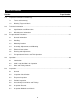
Table of Contents Section 1.0 2.0 3.0 4.0 5.0 Page Number Important Information and Warnings…………………………………………….……………………. 4 1.1 Terms and Summary 1.2 Warning Tags and Labels Technical Information …………………………….…………………………………………………….. 8 2.1 Specifications and Dimensions 2.2 Miscellaneous Information Pre-operational Procedures……………………………………………………………………….….. 21 3.1 General Information 3.2 Handling 3.3 Mounting Location 3.4 Assembly, Adjustments and Mounting 3.5 Electrical Connections 3.
Section 6.0 Page Number Maintenance & Handling………………………………………………………………………….…… 53 6.1 Lubrication 6.2 Hoist Motor Brake 6.3 Trolley Motor Brake Wire Rope 6.4 Storage 6.5 Outdoor Installation 7.0 Troubleshooting………………………………………………………………………………………… 64 8.0 Warranty………………………………………………………………………………………………….
1.0 Important Information and Warnings 1.1 Terms and Summary This manual provides important information for personnel involved with the installation, operation and maintenance of this product. Although you may be familiar with this or similar equipment, it is strongly recommended that you read this manual before installing, operating or maintaining the product. Danger, Warning, Caution and Notice - Throughout this manual there are steps and procedures that can present hazardous situations.
Equipment described herein is not designed for and MUST NOT be used for lifting, supporting, or transporting people, or for lifting or supporting loads over people. Equipment described herein should not be used in conjunction with other equipment unless necessary and/or required safety devices applicable to the system, crane, or application are installed by the system designer, system manufacturer, crane manufacturer, installer, or user.
HAZARDOUS VOLTAGES ARE PRESENT IN THE CONTROL BOX, OTHER ELECTRICAL COMPONENTS, AND CONNECTIONS BETWEEN THESE COMPONENTS. Before performing ANY mechanical or electrical maintenance on the equipment, de-energize (disconnect) the main switch supplying power to the equipment; and lock and tag the main switch in the de-energized position. Refer to ANSI Z244.1, “Personnel Protection – Lockout/Tagout of Energy Sources”. Only trained and competent personnel should inspect and repair this equipment.
1.2 Warning Tag and Labels The warning tag illustrated below in Figure 1-1 is supplied with each hoist and trolley shipped from the factory. If the tag is not attached to the pendant cord for your hoist/trolley, order a tag from your dealer and install it. Read and obey all warnings attached to this Hoist/Trolley. Tag is not shown actual size.
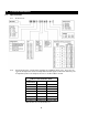
2.0 Technical Information 2.1 Specifications 2.1.1 Product Code: 2.1.2 Hoist and Trolley Size – The RH hoists and trolleys are available in 4 basic sizes. These sizes are referred to throughout this manual to identify what information applies to which hoist and trolley. The th 10 digit in the product code designates the sizes as shown in Table 2-1 below.
2.1.3 Operating Conditions and Environment Temperature Range: Humidity: Electrical Enclosure Rating: Brake Enclosure Rating: Supply Voltage: Control Voltage: 2.1.
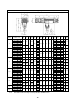
Table 2-3 Deck/Base Mounted or Lug Suspended Hoists – Dimensions* Capacity (Tons) 2 Product Code L L1 N P ∅Q R S1 S2 S3 S4 (in) (in) (in) (in) (in) (in) (in) (in) (in) (in) 3.9 10.4 5.9 63.4 6.3 22.2 6.5 20.3 48.6 3.9 10.4 5.9 6.5 RH02D-204D- 25.6 16.5 RH03D-234H- RH03D-334H- RH05D-234G- RH05D-334G- RH05D-234M- RH05D-334M- RH05D-464J- RH05D-924J- RH05D-524P- RH05D-X54P- 13.6 9.1 RH02D-294D- RH03D-853E- 9.8 27.2 18.1 15.4 25.6 16.
Table 2-4 Standard Headroom Trolley Hoists – Hoist Specifications Lifting Speed Capacity (Tons) Lift Product Code (ft/min) (ft) Reeving Rope** (parts/ reeving) 2 3 5 7 1/2 10 15 20 20 RH02S-294C-- 29 RH02S-204D-- 20 RH02S-294D-- 29 RH02S-393A-- 39 RH02S-793A-- 79 RH03S-204C-- 20 RH03S-294C-- 29 RH03S-234H-- 23 RH03S-334H-- 33 RH03S-463E-- 46 RH03S-853E-- 85 RH05S-234G-- 23 RH05S-334G-- 33 RH05S-234M-- 23 RH05S-334M-- 33
Table 2-5 Standard Headroom Trolley Hoists – Trolley Specifications Traversing Motors Capacity (Tons) Product Code Standard Flange Range B* (in) Single Speed Single Speed Dual Speed 40 ft/min 64 and 80 ft/min 64/16 and 80/20 ft/min Output (Hp) Rated Current (amps) @460V @230V Output (Hp) Rated Current (amps) @460V @230V Output (Hp) Rated Current (amps) @460V @230V RH02S-204C-- RH02S-294C-- 2 RH02S-204D-- RH02S-294D-- 3.54 to 11.02 0.32 1.1 2.2 0.6 1.1 3.0 0.6/0.13 1.
Table 2-6 Standard Headroom Trolley Hoists – Dimensions Note: Standard headroom trolleys are suitable for use on S or W shaped beams. Refer to Table 2-5 for flange range dimension B. Capacity (Tons) 2 Product Code C C1 C2 D D1 E E1 E2 I1 ∅R S1 S2 S3 (in) (in) (in) (in) (in) (in) (in) (in) (in) (in) (in) (in) (in) 10.4 RH02S-204C-- 20.3 3.9 RH02S-294C-- 35 6.3 22.8 20.3 3.9 10.4 6.3 22.8 RH02S-204D-- RH02S-294D-- 32.7 6.7 3.3 11.6 2.4 14.
2.1.
Table 2-8 Ultra-Low Headroom Trolley Hoists – Trolley Specifications Traversing Motors Capacity (Tons) Standard Flange Width B Product Code Single Speed Single Speed Dual Speed 40 ft/min 64 and 80 ft/min 64/16 and 80/20 ft/min Output (in) (Hp) Rated Current (amps) @460V @230V Output (Hp) Rated Current Output (amps) @460V @230V (Hp) Rated Current (amps) @460V @230V RH02U-204C-- RH02U-294C-- 2 RH02U-204D-- RH02U-294D-- 3.54 to 15.75 0.32 1.1 2.2 0.6 1.1 3.0 0.6/0.
Table 2-10 Ultra-Low Headroom Trolley Hoists – Dimensions Note: Ultra-Low headroom trolleys are suitable for use on S or W shaped beams. Refer to Table 2-8 for flange range dimension B. Refer to Table 2-9 for headroom dimension E. Capacity (Tons) 2 Product Code D D1 D2 E1 E2 I1 ∅R S1 S2 S3 (in) (in) (in) (in) (in) (in) (in) (in) (in) (in) 15.6 20.3 3.9 10.4 14.4 35.0 6.3 22.8 3.9 10.4 RH02U-204D-- RH02U-294D-- 6.7 3.3 11.6 17.3 9.1 22.8 9.3.
2.2 Miscellaneous Information Table 2-11 Eye Bolt and Attachment Point – Dimensions For Deck/Base Mounted or Lug Suspended Hoists Note: Eyebolts are suitable for deck/base mounted or lug suspended applications. Eyebolt kits include four eyebolts and all necessary hardware. See Table 2-3 for dimensions I and I1. Capacity (Tons) Product Code A A1 B1 B2 B3 B4 B5 ∅F G1 M1 (in) (in) (in) (in) (in) (in) (in) (mm) (in) (mm x pitch) 0.79 0.79 0.83 0.83 1.38 1.38 1.85 20 2.
Table 2-12 Bottom Hook – Dimensions Capacity (Tons) Product Code a b c d e f g h (in) (in) (in) (in) (in) (in) (in) (in) 2.2 1.8 1.9 1.5 2.2 2.5 1.5 5.7 1.7 1.4 1.5 1.1 1.9 2.1 1.3 4.7 2.2 1.8 1.9 1.5 2.2 2.5 1.5 5.7 2.6 2.1 2.3 1.8 2.5 2.8 1.7 6.7 2.2 1.8 1.9 1.5 2.2 2.5 1.5 5.7 2.6 2.1 2.3 1.8 2.5 2.8 1.7 6.7 3.5 2.8 3.0 2.4 3.1 3.5 2.0 8.9 2.6 2.1 2.3 1.8 2.5 2.8 1.7 6.7 3.5 2.8 3.0 2.4 3.1 3.5 2.0 8.9 3.5 2.8 3.
Table 2-13 Reaction Forces at Rated Load Deck/Base Mounted or Lug Suspended Hoists Deck/Base Mounted or Lug Suspended Attachment Point Reaction Forces Capacity (Tons) 2 3 5 7 1/2 10 15 20 Standard or Ultra-Low Headroom Trolley Hoist Standard Headroom Trolley Wheel Reaction Forces Ultra- Low Headroom Trolley Wheel Reaction Forces Product Code R1 (lbs) R2 (lbs) Product Code R1 (lbs) R2 (lbs) Product Code R1 (lbs) R2 (lbs) RH02D-204C- 1483 683 RH02S-204C-- 1600 665 RH02U-204C--
Table 2-14 Trolley Wheel – Dimensions Note: See Table 2-13 for reaction forces R1 and R2.
3.0 Pre-operational Procedures 3.1 General Information 3.1.1 When the RH trolley hoist is incorporated into lifting systems utilizing other equipment, follow and complete all pre-operational procedures and instructions provided with the equipment. Special wiring considerations must also be taken to complete the integration of the RH trolley hoist into the system. 3.1.2 The RH is generally delivered pre-assembled and shrink-wrapped on a pallet or in a wooden crate (see Figure 3-1).
3.2.2 Lift points – The deck mounted/lug suspended, standard headroom and ultra-low hoists and trolleys are equipped with lifting lugs to facilitate lifting the trolley hoist with a hoist or crane (see Figure 3-4). During lifting do NOT support the trolley hoist any other way. Figure 3-4 Lift Points 3.3 Mounting Location 3.3.1 Prior to mounting the trolley and hoist ensure that the trolley beam and its supporting structure are adequate to support the trolley, hoist and its loads.
3.3.5 3.3.6 Ensure that there is adequate vertical and horizontal clearance along the entire range of the trolley hoist’s motion (see Figure 3-7). See Section 6.6 for outdoor installation considerations. Refer to Table 2-3 for dimensions I and I1. Deck Mounted Lug Suspended Figure 3-5 Optional Eyebolt Kits Refer to Table 2-3 for dimensions I and I1.
3.4 Assembly, Adjustments and Mounting 3.4.1 Deck mounted configuration installation using the optional Eyebolt kit: 1) Make sure the mounting location complies with Section 3.3. 2) Refer to Figure 3-8 and Table 3-1. 3) With the hoist properly supported (see Section 3.2) remove the Socket Bolts (B), Attachment Plates (C) and Pins (A) from the 4 mounting slots points located on the bottom of the hoist’s housing.
3.4.2 Lug suspended configuration installation using the optional Eyebolt kit: 1) Make sure the mounting location complies with Section 3.3. 2) Refer to Figure 3-9 and Table 3-1. 3) With the hoist properly supported (see Section 3.2) remove the 4 Screws (J) and 2 Socket Bolts (K) attaching the Dust Covers (H) and Limit Switch Channel (L). DO NOT remove the bolts attaching the Limit Switches to the Limit Switch Channel and DO NOT remove the Angle Brackets from the hoist body.
3.4.3 Standard Headroom Trolley Installation 1) Make sure the mounting location complies with Section 3.3. 2) Each Stirrups (H) has sufficient clamping force on the Load Bars (J) with only two bolts. The third bolt cannot be installed in some cases because of interference with the suspension of the hoist (see Figure 3-10). 3) Install any additional devices, if any (power supply cords or pendants, for instance – see Section 3.5) onto the trolley hoist.
6) Adjust the trolley for the beam’s flange width as follows: Refer to Table 3-2 and select dimensions “A” and “C” corresponding to the beam’s flange width “B”. Loosen the Screws (D) that attach the Stiffening Plates (E) to Side Plates (F) and loosen the Lock-Nuts (G) on the Stirrups (H) that secure the Side Plates (F) to the Load Bars (J) so that the Side Plates (F) can move freely along the Load Bars (J) (see Figures 3-14 and 3-15).
Table 3-2 Standard Headroom Trolley Adjustment Dimension (continued) Adjustment Dimension (Inch) Beam Flange, B Trolley Size 1 Trolley Size 2 Trolley Size 3 Trolley Size 4 Hoist Size 1 4/1 Hoist Size 1 2/1 Hoist Size 2 2/1 Hoist Size 2 4/1 Hoist Size 3 2/1 Hoist Size 3 4/1 Hoist Size 4 2/1 Hoist Size 4 4/1 (mm) (inch) A C A C A C A C A C A C A C 143 5 5/8 5.18 2.97 4.67 3.48 5.26 2.89 4.48 2.88 6.06 2.88 4.79 2.97 6.44 2.89 A C 2.36 149 5 7/8 5.05 2.85 4.54 3.
Figure 3-14 Loosen Stiffener Plates Figure 3-15 Move Side Plates 7) Using a forklift or another suitable means, position the pallet so that the horizontal axis of the beam is parallel to the horizontal axis of the hoist (see Figure 3-16). 8) Temporarily slide the Side Plates (F) OPPOSITE the trolley motor(s) along the Load Bars (J) so that the Distance between the faces of the trolley wheel is wider than the beam flange (see Figure 3-17). 9) This applies to standard headroom trolleys only.
Figure 3-16 Positioning the Trolley Hoist Figure 3-17 Spread Side Plates Figure 3-18 Place Wheels on Beam Figure 3-19 Verify Proper Adjustment Table 3-3 Torque Values Torque Value (ft-lbs) Trolley Size Load Bar Lock-Nuts (G) Stiffener Screws (D) 1 23 9 30 2 39 18 3 94 49 4 184 75
3.4.4 Ultra-Low Headroom Trolley Installation 1) Make sure the mounting location complies with Section 3.3. 2) Install any additional devices, if any (power supply cords or pendants, for instance – see Section 3.5) onto the trolley hoist. If the trolley hoist is not secured to a pallet, place and secure it to one making sure that the trolley hoist is completely stable (see Figure 3-20). 3) Remove the Bottom Block from the pallet/packing and place it on the ground.
7) When installing the trolley hoist on a beam, ALWAYS raise the hoist into position with the trolley and hoist assembled together and securely attached to a pallet. Raise the trolley and hoist with a forklift, lifting platform, or other similar means. NEVER use slings to raise and install the trolley hoist onto the beam (see Figure 3-22).
14) Lower the pallet just enough until the trolley wheels are resting on the beam flange. 15) Check that all 4 trolley wheels rest correctly on the beam and that the clearance between the wheel edge and the edge of the beam is 5/64 inch (2 mm) maximum at all 4 wheels (see Figure 3-28). 16) Remove the straps/ropes securing the trolley hoist to the pallet and lower the pallet to the ground. 17) Reattach the Spacers (M) to the Stirrups (F).
3.5 Electrical Connections 3.5.1 3.5.2 3.5.3 3.5.4 Ensure that the voltage of the electric power supply is proper for the hoist or trolley. Do NOT apply electronic soft-start control or voltage varying controls to the RH’s lifting or traversing motors. Use of such devices may cause the motor brake and other electrical components to malfunction. For variable frequency drives contact Harrington for more information.
3.5.5 Installing Pendant 1) Refer to Figure 3-30, the wiring diagram and the interconnection diagram provided with the Hoist. 2) Remove Control Cover (A) or open the metal electrical enclosure. 3) Access to Terminal Strip: For hoists with metal electrical enclosure the terminal strips are accessible upon opening the enclosure lid. For hoists with the integral electrical enclosures (plastic cover), the Terminal Strips are located on the back side of the Panel (F).
3.6 Reeving and Adjustments 3.6.1 Reeving the bottom hook 1) Working from a scaffolding or lifting platform, remove the Retaining Ring (B) and Load Limiter Pin (D) from the Terminal Head Crossbar (A). Let the Load Limiter (C) rotate downward and remove the Terminal Head (F) from the Load Limiter (C) by pulling out the Terminal Head Pin (E). (see Figure 3-31). 2) From the ground, press the down button on the pendant until there is sufficient rope unwound to reeve the hoist.
Figure 3-33 Install Wire Rope on Terminal Head 3.6.2 Figure 3-34 Install Rope Clamp Figure 3-35 Install Terminal Head Adjusting the Limit Switches: 1) The maximum upper and lower Limit Switch (B, C) adjustments are marked in red on the Section Bar (D). NEVER adjust the limit switches past the red marks (Figure 3-36). 2) The upper Limit Switch (B) MUST be adjusted to prevent the collision of the load and/or Bottom Block with any part of the hoist, structure or girder(s) (Figure 3-37).
8) Check, according to the foreseen configuration, that the height of approach of the hook going up is not less than that stated in Table 2-3, 2-6 or 2-9 (dimension “H”, “H1” or “E”).
3.7 Pre-operational Checks and Trial Operation 3.7.1 Refer to the hoist’s (and trolley's) Nameplate(s) and record the Product Code(s), and Serial Number(s) in the space provided on the cover of this manual. 3.7.2 Perform pre-operational checks for the trolley hoist: 3.7.3 3.7.4 Confirm the adequacy of the rated capacity for all slings, chains, wire ropes and all other lifting attachments before use.
4.0 Operation 4.1 Introduction DO NOT WALK UNDER A SUSPENDED LOAD HOIST OPERATORS SHALL BE REQUIRED TO READ THE OPERATION SECTION OF THIS MANUAL, THE WARNINGS CONTAINED IN THIS MANUAL, INSTRUCTION AND WARNING LABELS ON THE HOIST OR LIFTING SYSTEM, AND THE OPERATION SECTIONS OF ANSI/ASME B30.16 and ANSI/ASME B30.10. THE OPERATOR SHALL ALSO BE REQUIRED TO BE FAMILIAR WITH THE HOIST AND HOIST CONTROLS BEFORE BEING AUTHORIZED TO OPERATE THE HOIST OR LIFTING SYSTEM.
The operation of an overhead hoist involves more than activating the hoist’s controls. Per the ANSI/ASME B30 standards, the use of an overhead hoist is subject to certain hazards that cannot be mitigated by engineered features, but only by the exercise of intelligence, care, common sense, and experience in anticipating the effects and results of activating the hoist’s controls.
Improper operation of a hoist can create a potentially hazardous situation which, if not avoided, could result in minor or moderate injury, or property damage. To avoid such a potentially hazardous situation THE OPERATOR SHALL: • Maintain a firm footing or be otherwise secured when operating the hoist. • Use the hoist manufacturer’s recommended parts when repairing the unit. • Check brake function by tensioning the hoist prior to each lift operation.
5.0 Inspection 5.1 General 5.1.1 5.2 The inspection procedure herein is based on ANSI/ASME B30.16. The following definitions are from ANSI/ASME B30.16 and pertain to the inspection procedure below. Designated Person – a person selected or assigned by the employer or employer’s representative as being competent to perform the specific duties.
5.2.4 PERIODIC Inspection – visual inspection by a designated person with intervals per the following criteria: Table 5-2 Periodic Inspection Intervals 5.3 Service Hoist and Trolley Interval Normal Service Monthly Heavy Service Weekly to Monthly Severe Service Daily to Weekly Special or Infrequent Service As recommended by a qualified person before the first such occurrence and as directed by the qualified person for any subsequent occurrences.
5.4 Periodic Inspection 5.4.1 Inspections should be made on a PERIODIC basis in accordance with Table 5-4, “Periodic Inspection.” A designated person shall make evaluation and resolution of the results of PERIODIC Inspections such that the hoist is maintained in safe working condition. 5.4.2 For inspections where load suspension parts of the hoist/trolley are disassembled, a load test per ANSI/ASME B30.16 must be performed on the hoist/trolley after it is re-assembled and prior to its return to service.
5.6 5.7 Inspection Records 5.6.1 Dated inspection reports and records should be maintained at time intervals corresponding to those that apply for the hoist’s PERIODIC interval per Section 5.2.4. These records should be stored where they are available to personnel involved with the inspection, maintenance, or operation of the hoist/trolley. 5.6.
Table 5-5 Hoist (and Trolley) Inspection Methods and Criteria (continued) Item Method Criteria Action Hook Block Sheave(s) and Shaft Visual, Function Sheave(s) should be free of significant wear. Sheave surfaces should be free of nicks, gouges, dirt and grime. Bearing parts and surfaces of Sheave and Shaft should not show significant wear. Sheave should rotate freely with no roughness or significant free play. Clean/lubricate, or replace as required.
Table 5-5 Hoist (and Trolley) Inspection Methods and Criteria (continued) Item Method Criteria Action The full length of the Wire Rope must be inspected for rope diameter, Broken strands or wires, and condition.
Table 5-5 Hoist (and Trolley) Inspection Methods and Criteria (continued) Item Method Criteria Action Trolley Wheel Tread Visual, Measure Diameter of the tread surface should not be less than 5% of its original diameter as new. Replace. Trolley Wheel Gear Visual Teeth should not be cracked, damaged, or excessively worn. Replace. Load Bar Visual, Measure Load Bar should be free of significant wear, cracks, nicks and gouges. Load Bar should not be bent. Replace.
Table 5-6 Bottom Hook Dimensions g1 Measured When New: _____________________ Hook Identifier "u" Dimension inch (mm) "t" Dimension inch (mm) Nominal "g1" Dimension* inch (mm) Standard Discard Standard Discard A or B (2 Falls) 1.50 (38) 1.46 (37) 1.39 (35.2) 1.14 (29) 1.08 (27.6) C or D (4 Falls) 1.77 (45) 1.89 (48) 1.80 (45.6) 1.50 (38) 1.42 (36.1) E or F (2 Falls) 1.77 (45) 1.89 (48) 1.80 (45.6) 1.50 (38) 1.42 (36.1) G or H (4 Falls) 1.97 (50) 2.28 (58) 2.17 (55.1) 1.
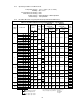
Table 5-7 Wire Rope Wear Dimensions Maximum Allowable Number of Broken Wires Rope Diameter Hoist Size Standard (mm) Discard (mm) (in) Normal 1 For 6xDia. Length For 30xDia. Length (mmspec.) No. Broken Wires Length Length (in) No. Broken Wires 7-B 3 1.7 6 8.3 7-M 3 1.7 6 8.3 7-A 3 1.7 6 8.3 Rope Rope Construction 7 6.6 0.26 Anti-revolving Normal 8 7.6 0.30 Anti-revolving 2 Normal 9 8.4 0.33 Anti-revolving 12 11.2 0.44 Normal Anti-revolving 3 13 12.2 0.
Table 5-8 Wire Rope Wear Dimensions (continued) Maximum Allowable Number of Broken Wires Rope Diameter Hoist Size For 6xDia. Length For 30xDia. Length (mmspec.) No. Broken Wires Length Length (in) No. Broken Wires 15-M 14 3.5 29 17.7 15-A 14 3.5 29 17.7 15-A 2 3.5 4 17.7 16-B 7 3.8 14 18.9 16-M 7 3.8 14 18.9 16-A 7 3.8 14 18.9 Rope Standard Rope Construction Discard (mm) (mm) (in) 15 14.0 0.55 Normal Anti-revolving 4 Normal 16 14.9 0.
6.0 Maintenance and Handling 6.1 Lubrication 6.1.1 6.1.2 6.1.3 6.1.4 6.2 Wire Rope: For proper performance the Wire Rope must be maintained in a clean and well lubricated condition. The rope should be lubricated every 3 months (more frequently for heavier usage or severe conditions). To lubricate the rope, first remove any dirt, grime, moisture or other accumulations of contaminates. Then coat the Wire Rope with Agip 360 EP/F oil or equivalent.
3) Check that the brake adjustment has been performed correctly. Complete the brake test, first with no load and then with a nominal load (see Table 5-8). 4) Readjust the brake as necessary. 5) It is recommended that the brake be replaced after 3 adjustments.
6.3 Trolley Motor Brake 6.3.1 6.3.2 The Trolley Brake adjustment can be accomplished 2 ways: External Method – External adjustment in the case of moderate wear or when changing the brake pre-sets. Internal Method – Internal adjustment is required after the External method does not provide enough braking. This usually occurs when brake wear exceeds 1mm.
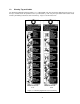
Figure 6-6 6.3.4 Internal Method – The internal method allows the braking to be increased as required. 1) Remove the Lock-Nut (C), Fan (D), Snap Ring (F), Pressure Washer (G), Spring (H) and all Thickness Washers (E) (see Figure 6-5 and 6-6). 2) Unscrew and remove the Hexagonal Spacers (J) and Nuts then remove the Motor Cover (P). Carefully, so as not to damage the rotor and/or the winding, slide the Rotor (N) with Brake Block (K) out of the motor completely (see Figure 6-7).
6.4 Wire Rope 6.4.1 Lubrication and Cleaning – Refer to Section 6-1. 6.4.2 Be certain that the replacement wire rope is obtained from Harrington Hoists, Inc. and is the correct wire rope for the hoist. If the wire rope is being replaced due to damage or wear out, destroy the old rope to prevent its reuse. 6.4.3 Wire Rope Removal 1) 2) 3) The hoist must be properly powered and operational in order to perform the following procedures.
9) Remove the Dust Cover (K) by unscrewing the Dust Cover Screws (J) (see Figure 6-13). 10) Gain access to the Rope Guide and associated components. For OTHER THAN 4/1 Ultra-Low Headroom Version: Remove, by lifting out, the Anchorage Cross Head (A) (includes the pulley assembly for 4/1 part/reeved hoists) after removing the Safety Screws (L). Take care not to disconnect or damage the overload device (C) (see Figure 6-14). Secure the Anchorage Cross Head (A) to the Bottom Bracket (M) (See Figure 6-15).
13) Unscrew the Nuts (X) remove the Screws (V) and the Springs (W) from the Rope Guide Ring Halves (P and Q), then remove the Ring Halve (Q) (see Figure 6-19). 14) Loosen the Screws (A1) of the Wire Rope Clamps (B1) and take out the Wire Rope and Ring Half (P) (see Figure 6-20). For 4/1 Ultra-Low headroom versions it is necessary to rotate the Ring Half (P) over the top of the drum to remove it from the hoist (see Figure 6-21).
6.4.4 1) 2) Wire Rope Installation The hoist must be properly powered and operational in order to perform the following procedures. When replacing Wire Rope, check for wear on mating parts, i.e. Drum, Sheaves, Hook Block Sheaves and replace if necessary. 3) ALWAYS unwind the roll of the new Wire Rope without kinks or bends (see Figure 6-22). 4) Examine the Wire Rope Guide Ring Halves (P) and (Q) and the Drum after cleaning/degreasing thoroughly.
7) Press the “UP” button on the Pendant to wind the Wire Rope onto the Drum. Use protective gloves to keep the Wire Rope constantly taut and well placed in the Drum grooves, letting the Wire Rope wind around for at least 10 times (see Figure 6-25). 8) Without loosening the tension on the Wire Rope, clamp a weight onto the Wire Rope below the Rope Guide, taking care not to damage the Wire Rope.
10) Insert the Wire Rope Clamp Runners (Z) piece by piece, into the slot on the side of the Rope Guide Ring (P) (see Figure 6-28). 11) Reinstall the Limit Switch Actuators (N) onto the Rope Guide Ring Halves (P) and (Q) and tighten the Screws (R) (see Figure 6-29). 12) Reposition the Wire Clamping Spring (T) on the Runners (Z). Use the Wire Rope Guide Clamping Tool (S), to pull the Spring taut. Couple the ends of the Clip (U) onto the Spring using the pliers (see Figure 6-30).
14) Carry out again all the sequences described in Section 3.6 “Reeving and Adjustments”. Lubricate the Wire Rope, the Rope Guide and Drum (see Section 6.1). Figure 6-33 Figure 6-32 6.5 6.6 Storage 6.5.1 The storage location should be clean and dry. 6.5.2 Care should be take to not damage any of the electrical power cords or fittings. Outdoor Installations 6.6.
7.0 Troubleshooting HAZARDOUS VOLTAGES ARE PRESENT IN THE HOIST AND IN CONNECTIONS BETWEEN COMPONENTS. Before performing ANY troubleshooting on the equipment, de-energize the supply of electricity to the equipment, and lock and tag the supply device in the de-energized position. Refer to ANSI Z244.1, “Personnel Protection Lockout/Tagout of Energy Sources.” Only Trained and competent personnel should inspect and repair this equipment.
Table 7-1 Troubleshooting Guide Symptom Cause Remedy Down circuit open Check circuit for loose connections. Check down limit switch for malfunction. Broken conductor in pendant cord Check the continuity for each conductor in the cable. If one is broken, replace entire cable. Faulty magnetic contactors Check coils for open or short circuit. Check all connections on motor circuit. Check for burned contacts. Replace as needed. Faulty switch in pendant Check electrical continuity.
Table 7-1 Troubleshooting Guide Symptom Cause Remedy Contactor contacts arcing Check for burned contacts. Replace as needed. Loose connection in circuit Check all wires and terminals for bad connections. Replace as needed. Broken conductor in Pendant Cord Check for intermittent continuity in each conductor of the Pendant Cord. Replace entire Pendant Cord if continuity is not constant. Trolley making loud noise.
8.0 Warranty Warranty explanation and terms. All products sold by Harrington Hoists, Inc.
www.harringtonhoists.com Harrington Hoists, Inc. 401 West End Avenue Manheim, PA 17545 Phone: 717-665-2000 Toll Free: 800-233-3010 Fax: 717-665-2861 Harrington Hoists – Western Division 2341 Pomona Rd.