
Instruction Manual

17
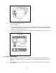
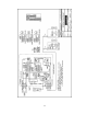
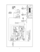
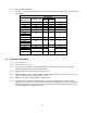
5.0 Parts List
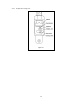
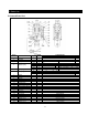
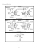
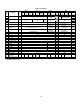
5.1 Internal Parts List
Load Limiter type Figure
Number
Part Name Type
Quantit
y
01H,
03S, 03H 05S 10S 15M 20S
30R 25M,30S 50R
1 Casing A 1
2 Casing B 1
3 Plunger 1
S-22 (x) (14)
L-22 (x) (14) (7)
H-22 (x) (9)
4* Belleville spring
H-25 (x) (10) (8)
(2 x 6)
(6) (15)
5 Spring support U 1
A
(x) (1) (3) (2)
B (x) (1) (2)
(1) (3)
6* Spring support D
C (x) (1)
7 Set nut 1
8 Plunger arm 1
9 Adjuster 1
10 Switch bracket 1
11 Switch 1
12 Insulation plate 1
13 Connector 2
14 Power supply cable 2C
1
15 Casing packing 1
16 Casing cover 1
17 Set screw 2
18 Socket bolt 2 M8x40x22(mm)
19 Socket bolt 1 M8x30x22(mm)
20 Nut 1 3-M8
21 Spring washer 4 2-M8
22 Machine screw 2 M4 x 24 x 24(mm)
23 Machine screw 2 M4 x 14 x 14(mm)
24 Machine screw 4 M5x10x10(mm)
*Quantities in parentheses.