EFFECTIVE: February 4, 2014 ELECTRIC CHAIN HOIST ER2 and NER2 SERIES 8 Ton through 20 Ton Capacity Code, Lot and Serial Number This equipment should not be installed, operated or maintained by any person who has not read and understood all the contents of this manual. Failure to read and comply with the contents of this manual can result in serious bodily injury or death, and/or property damage.
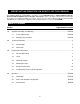
IMPORTANT INFORMATION ON HOW TO USE THIS MANUAL This OWNER’S MANUAL SUPPLEMENT is intended for use in combination with the “Owner’s Manual for Electric Chain Hoist ER2 and NER2 Series 1/8 through 5 Ton Capacity”. Refer to the Table of Contents below to determine the location(s) of information pertaining to your hoist. References to the “Owner’s Manual for Electric Chain Hoist ER2 and NER2 Series 1/8 through 5 Ton Capacity” will be designated by the use of the acronym “ER2OM”. Table of Contents Section 1.
Section 5.0 6.0 Page Number/Location Inspection…………………………….………………………………….…………..…….. 15 and ER2OM 5.1 General ER2OM 5.2 Inspection Classification ER2OM 5.3 Frequent Inspection ER2OM 5.4 Periodic Inspection ER2OM 5.5 Occasionally Used Hoists ER2OM 5.6 Inspection Records ER2OM 5.7 Inspection Methods and Criteria 15 and ER2OM Maintenance & Handling…………………………………………………….……………. 18 and ER2OM 6.1 Count/Hour Meter ER2OM 6.2 Lubrication 18 and ER2OM 6.3 Motor Brake 18 and ER2OM 6.
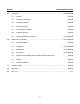
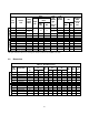
2.0 Technical Information 2.1 Specifications 2.1.1 Product Code 2.1.
Table 2-1 Hoist Specifications Cap. (Tons) Product Code (N)ER2080S* (N)ER2100L (N)ER2100L-LG (N)ER2100S (N)ER2150S (N)ER2200S 7.5 Single Speed 8 10 10 10 15 20 Dual Speed Lifting Speed (ft/min) 8 10 10 10 15 20 (N)ER2080SD* (N)ER2100LD (N)ER2100LD-LG (N)ER2100SD (N)ER2150SD (N)ER2200SD Output (Hp) Motor Rated Current (amps) 208V 230V 460V Load Chain Diameter (mm) x Chain Fall Lines Load Sheave Pockets 11.2 x 3 4.7 16.4 7.9 11 7.5 5.5 4.7 x 2 4.7 x 2 4.7 x 2 16.4 x 2 16.4 x 2 16.
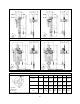
Figure 2-1 – NER2080S Figure 2-2 – NER2080SD Figure 2-3 – NER2100S Figure 2-4 – NER2100SD Table 2-3 Hook Dimensions* T = Top Hook B = Bottom Hook Units = in.(mm) Capacity Code Hook a b c d e g 080S B 3.3 (83.5) 2.2 (55.0) 2.9 (73.0) 1.9 (48.0) 3.3 (85.0) 2.4 (62.0) 100L, 100S T&B 3.3 (83.5) 2.2 (55.0) 2.9 (73.0) 1.9 (48.0) 3.3 (85.0) 2.4 (62.0) 150S T&B 4.1 (104) 2.8 (70.0) 3.4 87.0) 2.4 (60.0) 3.9 (100.0) 3.1 (79.0) 200S T&B 4.6 (118) 3.3 (83.0) 3.9 (99.5) 2.8 (70.
3.0 Preoperational Procedures 3.1 Gear Box 3.1.1 The gearbox is filled with the correct amount of oil at the time of shipment. The oil level must be verified prior to operation. The ER2 and NER2 hoists have different checking procedures. Refer to Section 6.3 of the ER2OM for specific checking procedures. Use the 050L Capacity Code to determine the correct “Check Distance” for the ER2 Large Capacity hoist. 3.1.2 Refer to Section 6.3 of the ER2OM when replacing the gear oil.
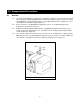
3.2 Chain 3.2.1 The quantity and location of the chain components including chain springs and stoppers depends on the hoist model and capacity. Never operate the hoist with incorrect, missing or damaged chain components. Refer to the hoist's nameplate, Table 3-2, and Figure 3-2 and ensure that all chain components are in the correct location and properly installed. 3.2.2 When the hoist is used without a chain container, the free end of the chain is attached to the hoist body as shown in Figure 3-2.
(N)ER2100S to (N)ER2200L (N)ER2080S to (N)ER2100L Figure 3-3 Installation of Chain Container 3.2.5 When using an optional steel chain container, refer to the instructions and/or assembly drawing(s) provided with the container for correct assembly and attachment. 3.2.6 Verify that the load chain is not twisted or tangled prior to operating the hoist. Make sure the bottom hook is not capsized. See Figure 3-4. Correct all chain irregularities before conducting the first hoist operation. 3.2.
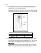
3.4.4 3.4.5 3.5 Lug Mounted ER2080S and ER2100L-LG – To maintain proper balance when the hoist is not loaded, it is necessary to install a stabilizing shaft to prevent the hoist from pivoting on the main support shaft. Refer to Figure 2-1 and Figure 2-2 for the size and location of the main support and stablizing holes in the hoist’s top suspension plates. Ensure that the fixed suspension point rests on the center of the hook’s saddle and that the hook’s latch is engaged.
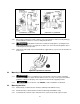
Power Supply Cable - Hoist Connection The Power Supply Cable connects to the hoist via a 4-pin (4P) plug and socket or a direct fitting depending on the product code. Make this connection as follows: Refer to Figure 3-5 or 3-6 depending on the product code. For ER2080S and ER2100L insert the 4P plug of the Power Supply Cable into the 4P Socket on the hoist and hand tighten the Lock Ring.
Figure 3-6 Pendant and Power Supply Cable Connections for ER2100S, ER2150S and ER2200S Figure 3-7 Power Supply Cable Festooning and Guide Wire Location 12
Power Supply Cable - Installation If the hoist is hook mounted to a fixed support ensure that the Power Supply Cable is properly installed and supported between the hoist and the electrical power supply. If the hoist is installed on a manual trolley, then the Power Supply Cable must be installed along the beam that the trolley runs on. For curved beams a special cable suspension system will be needed, and this instruction does not apply.
3.6 Preoperational Checks and Trial Operation 3.6.1 3.6.2 Refer to the hoist’s nameplate and record the hoist's Code, Lot and Serial Number in the space provided on the cover of this manual. Confirm the adequacy of the rated capacity for all slings, chains, wire ropes and all other lifting attachments before use. Inspect all load suspension members for damage prior to use and replace or repair all damaged parts. 3.6.
5.0 Inspection The information listed in this section is intended to supplement Section 5.7 of the ER2OM. Table 5-3 Hoist Inspection Methods and Criteria Use this table in conjunction with Table 5-3 of the ER2OM. The entries in this table replace in their entirety the corresponding entries in Table 5-3 of the ER2OM. Item Method Criteria Action Hooks - Fretting wear Measure The "u" and "t" dimensions should not be less than discard value listed in Table 5-4 Replace.
Table 5-4 Top Hook & Bottom Hook Dimensions “k” Measured When New: Top: _________________________ Bottom: ______________________ "u" Dimension inch (mm) "t" Dimension inch (mm) Nominal "k" Dimension* inch (mm) Standard Discard Standard Discard 080S 4.76(121) 2.86(72.6) 2.72(69) 1.89(48) 1.8(45.6) 100L, 100S 5.16(131) 3.43(87) 3.26(82.7) 2.36(60) 2.24(57) 150S 5..6(142) 3.91(99.4) 3.72(94.5) 2.76(70) 2.62(66.5) 200S 7.13(181) 4.4(112) 4.19(106.4) 2.8(71) 2.66(67.
Table 5-6 Chain Spring Length Dimensions “Length” - inch (mm) Capacity Code 080S, 100L, 100S, 0150S, 200S 17 Standard Discard 6.3 (160) 6.
6.0 Maintenance and Handling 6.2 Lubrication 6.2.1 Load Chain 6.2.2 Hooks and Suspension Components: 6.2.3 Refer to 6.2.1 of the ER2OM. Refer to 6.2.2 of the ER2OM. Gear Box: Refer to 6.3 of the ER2OM except use the following table for checking oil level. Table 6-1 ER2 (Mechanical Load brake Equipped) Gear Oil Check Distances Capacity Code Check Distance (inches) Check Distance (millimeters) 5.12 130 080S, 100L, 100S, 0150S, 200S 6.
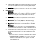
6.4 Load Chain 6.4.1 6.4.2 1) 2) 3) Lubrication and Cleaning – refer to Section 6.2 of ER2OM. Load Chain Replacement for ER2080S and ER2100L: The hoist must be properly powered and operational in order to perform the following procedures. Be certain that the replacement chain is obtained from Harrington and is the exact size, grade and construction as the original chain. The new load chain must have an odd number of links so that both its end links have the same orientation.
Figure 6-3 Chain Replacement for 080S and 100L 6.4.3 1) 2) 3) Load Chain Replacement for ER2100S, ER2150S and ER2200S: The hoist must be properly powered and operational in order to perform the following procedures. Be certain that the replacement chain is obtained from Harrington and is the exact size, grade and construction as the original chain. The new load chain must have an odd number of links so that both its end links have the same orientation.
11) Remove the remaining Stopper and Chain Spring from the old chain. Inspect and replace any damaged or worn parts. Install the Stopper and Chain Spring to the end of the new chain. Refer to Section 3.2 in this supplement for correct location. 12) For hoists without a chain container, attach the ends of the chain to Chain Guide A on each body with the socket bolt, and lock nut (see Figure 3-2). Ensure that all chain parts remain free of twists and correct any if found.
This Page Intentionally Left Blank 22
9.0 Parts List When ordering Parts, please provide the Hoist code number, lot number and serial number located on the Hoist nameplate (see fig. below). Reminder: Per sections 1.1 and 3.7.4 to aid in ordering Parts and Product Support, record the Hoist code number, lot number and serial number in the space provided on the cover of this manual. ER2/NER2 Series Nameplate The parts list is arranged into the following sections: Section Page 9.1 Housing and Motor Parts……………………………………………….………………………………………………..
9.
9.1 Housing and Motor Parts Figure No.
9.
9.2 Gearing Parts Figure No.
9.
9.3 Chain Parts Figure No.
9.
9.4 Bottom Hook Parts Figure No.
9.
9.4 Bottom Hook Parts Figure No.
9.
9.5 Electric Parts (Single Speed) Figure No.
9.
9.6 Electric Parts (Dual Speed) Figure No.
9.
9.7 Power Supply and Pendant Parts Figure No.
9.
9.7 Power Supply and Pendant Parts Figure No.
9.
9.8 Top Suspension Plate Parts Figure No.
9.
9.8 Top Suspension Plate Parts Figure No.
9.
9.9 Top Hook Parts Figure No.
9.
9.9 Top Hook Parts Figure No.
9.
9.9 Top Hook Parts Figure No.
9.
9.10 Control Station Parts (Plate Supension Type) Figure No.
9.
9.11 Control Station Parts (Top Hook Type) Figure No.
9.
9.12 Chain Container Parts Figure No.
9.
9.12 Chain Container Parts Figure No.
www.harringtonhoists.com Harrington Hoists, Inc. 401 West End Avenue Manheim, PA 17545 Phone: 717-665-2000 Toll Free: 800-233-3010 Fax: 717-665-2861 Harrington Hoists – Western Division 2341 Pomona Rd.