EFFECTIVE: December 13, 2012 ELECTRIC CHAIN HOIST ER2 and NER2 SERIES 1/8 Ton through 5 Ton Capacity Code, Lot and Serial Number This equipment should not be installed, operated, or maintained by any person who has not read and understood all the contents of this manual. Failure to read and comply with the contents of this manual can result in serious bodily injury or death, and/or property damage.
Table of Contents Section 1.0 2.0 3.0 4.0 5.0 Page Number Important Information and Warnings ……………………………………………………………………… 4 1.1 Terms and Summary 1.2 Warning Tags and Labels Technical Information…………………………………………………………………………….…………. 8 2.1 Specifications 2.2 Dimensions Preoperational Procedures ……………………………………………………………………………… 13 3.1 Gearbox 3.2 Chain 3.3 Mounting Location 3.4 Mounting the Hoist 3.5 Electrical Connections 3.6 VFD Setup (Dual Speed Only) 3.
Section 6.0 Page Number Maintenance & Handling …………………………………………………………………………………. 39 6.1 Count/Hour Meter 6.2 Lubrication – Load Chain, Hooks and Suspension 6.3 Lubrication – Gearbox 6.4 Motor Brake 6.5 Load Chain 6.6 Friction Clutch and Mechanical Load Brake with Friction Clutch 6.7 Storage 6.8 Outdoor Installation 6.9 Operational Environment 7.0 Troubleshooting …………………………………………………………………………………………… 47 8.0 Warranty …………………………………………………………………………………………………… 50 9.
1.0 Important Information and Warnings 1.1 Terms and Summary This manual provides important information for personnel involved with the installation, operation and maintenance of this product. Although you may be familiar with this or similar equipment, it is strongly recommended that you read this manual before installing, operating or maintaining the product. Danger, Warning, Caution and Notice Throughout this manual there are steps and procedures that can present hazardous situations.
Equipment described herein is not designed for and MUST NOT be used for lifting, supporting, or transporting people, or for lifting or supporting loads over people. Equipment described herein should not be used in conjunction with other equipment unless necessary and/or required safety devices applicable to the system, crane, or application are installed by the system designer, system manufacturer, crane manufacturer, installer, or user.
HAZARDOUS VOLTAGES ARE PRESENT IN THE CONTROL BOX, OTHER ELECTRICAL COMPONENTS, AND CONNECTIONS BETWEEN THESE COMPONENTS. Before performing ANY mechanical or electrical maintenance on the equipment, de-energize (disconnect) the main switch supplying power to the equipment; as well as lock and tag the main switch in the de-energized position. Refer to ANSI Z244.1, “Personnel Protection – Lockout/Tagout of Energy Sources”. Dual speed units incorporate a VFD as well as a Capacitor.
1.2 Warning Tags and Labels The warning tag illustrated below in Figure 1-1 is supplied with each hoist shipped from the factory. If the tag is not attached to your hoist’s pendant cord, order a tag from your dealer and install it. Read and obey all warnings attached to this hoist. Tag is not shown actual size.
2.0 Technical Information 2.1 Specifications Note: This Owners Manual is for the Enhanced Features Model ER and NER. This Enhanced Features Model is referred to as the ER2 and NER2 in this Owners Manual. Pendants are shown with optional Emergency Stop button. 2.1.1 Product Code 2.1.2 ER2 and NER2 Models - Harrington ER2 series hoists are available in two versions, the ER2 and NER2. These two versions differ with the presence of a mechanical load brake as standard equipment.
2.1.
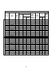
Table 2-1 Hoist Specifications Motor Capacity (Ton) DUAL SPEED SINGLE SPEED 1/8 Product Code Current Draw Lifting Speed Output (ft/min) (Hp) (amps) 208V or 230V 460V Load Chain Wire Diameter (mm) x Chain Fall Lines Load Sheave Pockets Net Weight (lbs) NER ER Weight for One Addnl. FT. of Lift (lbs) (N)ER2001H 55 0.75 3.4 1.7 4.3 x 1 6 60 62 0.28 1/4 (N)ER2003S 36 0.75 3.4 1.7 4.3 x 1 6 60 62 0.28 1/4 (N)ER2003H 53 1.2 4.8 2.5 6.0 x 1 5 79 82 0.
2.2 Dimensions Figure 2-2 Single Speed Hoist Dimensions (See Table 2-3) Figure 2-3 Dual Speed Hoist Dimensions (See Table 2-3) Table 2-2 Hook Dimension* T = Top Hook B = Bottom Hook Units = inch Capacity Code 001H, 003S, 003H, 005L, 005S Hook a b c d e g T&B 1.1 0.7 0.9 0.7 1.4 1.1 T 1.1 0.7 0.9 0.7 1.4 1.1 B 0.8 0.5 0.7 0.5 1.4 1.1 010L, 010S T&B 1.5 0.9 1.2 0.9 1.7 1.2 020C T&B 1.9 1.1 1.6 1.1 2.0 1.5 001HCC, 003SCC 015S 020L, 020S T 2.0 1.3 1.7 1.
Table 2-3 Hoist Dimensions Minimum Product Code a Headroom L* C (ft) DUAL SPEED SINGLE SPEED (in) b (in) d (in) e (in) i (in) NER ER NER ER NER ER NER ER g h (in) (in) (in) NER ER (N)ER2001H 13.8 8.2 18.8 22.2 12.6 13.6 8.6 12.0 10.2 10.2 1.1 3.9 3.7 4.6 (N)ER2003S 13.8 8.2 18.8 22.2 12.6 13.6 8.6 12.0 10.2 10.2 1.1 3.9 3.7 4.6 (N)ER2003H 14.6 8.2 20.0 23.3 13.7 13.7 9.5 12.8 10.5 10.5 1.1 4.4 4.2 4.2 (N)ER2005L 14.6 8.2 20.
3.0 Preoperational Procedures 3.1 Gearbox 3.1.1 The gearbox is filled with the correct amount of oil at the time of shipment. The oil level must be verified prior to operation. The ER2 and NER2 hoists have different checking procedures. Refer to Section 6.3 for specific checking procedures. 3.1.2 Refer to Section 6.3 when replacing the gear oil. 3.1.3 All ER2, mechanical load brake equipped hoists, are shipped with a separate air vented oil cap. This vented oil cap must be installed prior to use.
3.2 Chain 3.2.1 The quantity and location of the chain components including cushion rubbers, chain springs, and striker plates depend on the hoist model, capacity, and limits switches. Never operate the hoist with incorrect, missing, or damaged chain components. Refer to the hoist's nameplate, Table 3-1, as well as Figures 3-2, 3-3. Ensure that all chain components are in the correct location and properly installed. 3.2.
001H, 003S, 003H, 005L, 005S, 010L, 010S, 015S, 020L, 020S, 025S 020C, 030C, 050L Figure 3-3 Attachment of Chain to Hoist Body – No Chain Container 3.2.3 3.2.4 Optional Canvas or Plastic Chain Container - When the optional canvas chain container is selected, fully unfold and install it on the hoist body as shown in Figure 3-4.
3.2.5 3.2.6 When using an optional steel chain container, refer to the assembly drawing and instructions provided with the container for correct assembly and attachment. Verify that the load chain is not twisted or tangled prior to operating the hoist. Make sure the bottom hook on 2, 3 and 5 Ton double fall models is not capsized. See Figures 3-5 and 3-6. Correct all chain irregularities before conducting the first hoist operation.
3.4 Mounting the Hoist 3.4.1 Manual Trolley - Follow instructions in Owner’s Manual provided with the trolley. 3.4.2 Motorized Trolley - Follow instructions in Owner’s Manual provided with the trolley. 3.4.3 Hook Mounted to a Fixed Location - Attach the hoist’s top hook to the fixed suspension point. 3.4.4 3.5 Ensure that the fixed suspension point rests on the center of the hook’s saddle and that the hook’s latch is engaged. Electrical Connections 3.5.1 3.5.2 3.5.3 3.5.
Power Supply Cable - Installation If the hoist is hook mounted to a fixed support ensure that the Power Supply Cable is properly installed and supported between the hoist and the electrical power supply. If the host is installed on a manual trolley, then the Power Supply Cable must be installed along the beam that the trolley runs on. For curved beams a special cable suspension system will be needed, and this instruction does not apply.
3.6.1 To avoid a shock hazard, DO NOT perform ANY mechanical or electrical maintenance on the dual speed ( VFD control) trolley or hoist within 5 minutes of de-energizing (disconnecting) the trolley or hoist. This time allows the internal VFD capacitor to safely discharge. 3.6.2 Do Not remove power to the dual speed (VFD control) hoist or trolley during operation. 3.6.3 All dual speed hoists are equiped with a VFD. The VFD is used to control the high and low lifting speeds.
3.6.6 During operation the data display will exhibit illuminating or blinking data as shown in Figure 3-9. Figure 3-9 Illuminating/Blinking Display 3.6.7 The digital display uses a seven segment character to form the specific charaters used in the display. Table 3-3 shows the corresponding digital characters to its English eqivalent.
3.6.9 The Run Lamp display provides hoist “RUN” status. Table 3-5 shows the various “RUN” displays. Table 3-5 Run Lamp 3.6.10 All of the hoists have speed/frequency ranges that can be customized to a specific application. Refer to Table 3-6 for specific hoist speed/frequency ranges. To set custom speeds for an application, follow the procedure listed in Table 3-7.
Table 3-7 Dual Speed Hoist (w/VFD) Speed/Frequency Change Procedure Each dual speed hoist model has a range of available speeds/frequencies (upper and lower limits). Any value outside the range listed in Table 3-6 for your specific hoist is strictly prohibited. Speeds must be set such as Low [d1-01] and High [d1-02]. After parameters are changed, a “no load” operational check must be performed. Operational Step VFD Display 1. Energize the hoist. 2.
Table 3-8 Hoist VFD 2-Step/3-Step Infinitely Variable Parameter Setup Procedure Each VFD controlled hoist model has a range of available speeds/frequencies (upper and lower limits). Refer to Table 3-6 for a list of acceptable speeds/frequencies. Any value outside the range listed in Table 3-6 for your specific hoist is strictly prohibited. Speeds must be set such as Low [d1-01] and High [d1-02]. After parameters are changed, a “no load” operational check must be performed.
3.7 Preoperational Checks and Trial Operation 3.7.1 Confirm the adequacy of the rated capacity for all slings, chains, wire ropes and all other lifting attachments before use. Inspect all load suspension members for damage prior to use and replace or repair all damaged parts. 3.7.2 Verify and correct all chain irregularities prior to operating the hoist. Refer to Section 3.2. 3.7.3 Measure and record the “k” dimension of all hooks on hoist. See Table 5-4 under Section 5, “Inspection”. 3.7.
4.0 Operation 4.1 Introduction DO NOT WALK UNDER A SUSPENDED LOAD HOIST OPERATORS SHALL BE REQUIRED TO READ THE OPERATION SECTION OF THIS MANUAL, THE WARNINGS CONTAINED IN THIS MANUAL, INSTRUCTION AND WARNING LABELS ON THE HOIST OR LIFTING SYSTEM, AND THE OPERATION SECTIONS OF ANSI/ASME B30.16 and ANSI/ASME B30.10. THE OPERATOR SHALL ALSO BE REQUIRED TO BE FAMILIAR WITH THE HOIST AND HOIST CONTROLS BEFORE BEING AUTHORIZED TO OPERATE THE HOIST OR LIFTING SYSTEM.
The operation of an overhead hoist involves more than activating the hoist’s controls. Per the ANSI/ASME B30 standards, the use of an overhead hoist is subject to certain hazards that cannot be mitigated by engineered features, but only by the exercise of intelligence, care, common sense, and experience in anticipating the effects and results of activating the hoist’s controls.
Improper operation of a hoist can create a potentially hazardous situation which, if not avoided, could result in minor or moderate injury, or property damage. To avoid such a potentially hazardous situation THE OPERATOR SHALL: • Maintain a firm footing or be otherwise secured when operating the hoist. • Check brake function by tensioning the hoist prior to each lift operation. • Use hook latches. Latches are to retain slings, chains, etc. under slack conditions only.
4.3 Hoist Controls 4.3.1 For hoists mounted to motorized trolleys follow the control instruction included in the trolley's Owner's Manual. 4.3.2 Emergency Stop Button – Press the Emergency Stop Button to perform an emergency stop and lock-out of hoist motion controls or to reset the VFD as shown in Figure 4-1. Turn the Emergency Stop Button clockwise to unlock the controls and allow hoist operation. “Hbb” will appear on the dual speed unit’s VFD display when the Emergency Stop Button is depressed. 4.3.
5.0 Inspection 5.1 General 5.1.1 5.2 The inspection procedure herein is based on ANSI/ASME B30.16. The following definitions are from ANSI/ASME B30.16 and pertain to the inspection procedure below. Designated Person – a person selected or assigned as being competent to perform the specific duties to which he/she is assigned.
5.3 Frequent Inspection 5.3.1 Inspections should be made on a FREQUENT basis in accordance with Table 5-1, “Frequent Inspection.” Included in these FREQUENT Inspections are observations made during operation for any defects or damage that might appear between Periodic Inspections. Evaluation and resolution of the results of FREQUENT Inspections shall be made by a designated person such that the hoist is maintained in safe working condition.
5.5 Occasionally Used Hoists 5.5.1 5.6 5.7 Hoists that are used infrequently shall be inspected as follows prior to placing in service: Hoist Idle More Than 1 Month, Less Than 1 Year: Inspect per FREQUENT Inspection criteria in Section 5.3. Hoist Idle More Than 1 Year: Inspect per PERIODIC Inspection criteria in Section 5.4. Inspection Records 5.6.
Table 5-3 Hoist Inspection Methods and Criteria Item Criteria Action Visual, Function Bearing parts and surfaces should not show significant wear, and should be free of dirt, grime and deformations. Hook should rotate freely with no roughness. Clean/lubricate, or replace as required. Hooks - Yoke Assembly Visual Should be free of significant rust, weld splatter, nicks, and gouges. Holes should not be elongated. The difference between dimensions “a” (vertical) and “b” (horizontal) must be within .
Table 5-3 Hoist Inspection Methods and Criteria Item Method Criteria Action Measure The Connection Yoke Chain Pin should not have and apparent deformation. The “d” dimension should not be less than the discard value listed in Table 5-6. Replace. Cushion Rubber Visual Should be free of significant deformation. Replace. Chain Springs Visual Chain springs should not be deformed or compressed. Refer to Table 5-9 for Chain Spring dimensions. Replace.
Load Sheave Visual Pockets of Load Sheave should be free of significant wear. Refer to Table 5-8 for Load Sheave wear dimensions. Replace. Pendant - Housing Visual Pendant housing should be free of cracks and mating surfaces of parts should seal without gaps. Replace. Pendant - Wiring Visual Wire connections to switches in pendant should not be loose or damaged.
Table 5-4 Top Hook & Bottom Hook Dimensions “k” Measured When New: Top: _________________________ Bottom: ______________________ "u" Dimension inch (mm) "t" Dimension inch (mm) Nominal "k" Dimension* inch (mm) Standard Discard Standard Discard 001H, 003S, 003H, 005L, 005S 1.77 (45.0) 0.93 (23.5) 0.88 (22.3) 0.69 (17.5) 0.65 (16.6) 010L, 010M, 010S 1.97 (50.0) 1.22 (31.0) 1.16 (29.5) 0.89 (22.5) 0.84 (21.4) Capacity Code 015S 2.36 (60.0) 1.44 (36.5) 1.37 (34.7) 1.04 (26.5) 0.
Table 5-5 Chain Wear Dimensions “P” Dimension inch (mm) Capacity Code “d” Dimension inch (mm) Standard Discard Standard Discard 001H, 003S 2.38 (60.5) 2.46 (62.5) 0.17 (4.3) 0.15 (3.9) 003H, 005L, 005S 3.31 (84.0) 3.41 (86.5) 0.24 (6.0) 0.21 (5.4) 010L, 010S, 020C 4.25 (108.0) 4.38 (111.2) 0.30 (7.7) 0.27 (6.9) 015S, 020L, 020S, 030C 5.63 (143.0) 5.80 (147.2) 0.40 (10.2) 0.36 (9.2) 025S, 030L, 050L 6.18 (157.0) 6.37 (161.7) 0.44 (11.2) 0.40 (10.
Table 5-7 Motor Brake Wear/Gap Dimensions "Gap" Dimension - inch (mm) Hoist Speed Capacity Code Discard 001H to 020L 0.030 (0.75) 020S to 050L 0.043 (1.10) 001HD, 003SD, 005LD 0.024 (0.60) 003HD, 005SD to 020LD 0.016 (0.40) 020SD to 050LD 0.020 (0.50) Single Dual Figure 5-4 Hub Joint Note: Hub Joint shown for 0.75HP motor. All other motors use splined Hub Joint.
Table 5-8 Load and Idle Sheave Wear Dimensions Load Sheave Idle Sheave “Thickness” - inch (mm) Capacity Code Standard Discard 001H, 003S, 003H 0.06 (1.5) 0.04 (1.0) 005L, 005S 0.12 (3.0) 0.08 (2.0) 010L, 010S, 020C 0.18 (4.5) 0.12 (3.0) 015S, 020L, 020S, 030C 0.26 (6.5) 0.17 (4.3) 025S, 030L, 050L 0.29 (7.3) 0.19 (4.9) Table 5-9 Chain Spring Length Dimensions Capacity Code “Length” - inch (mm) Standard Discard 020C 3.94 (100) 3.74 (95) 020L 2.76 (70) 2.64 (67) 020S 3.
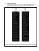
6.0 Maintenance and Handling 6.1 Count/Hour Meter A count/hour function is included in all NER2/ER2 hoists. A Count/Hour Meter is included in the single speed hoists and a count/hour function is one of the VFD parameters in the dual speed hoists. 6.1.1 Single Speed – The Count/Hour (C/H) Meter located on the electrical control panel records the hoist's “ON” time and number of starts. To view these values, press the button on the C/H Meter one time. The display will then show a total of 3 values.
6.1.3 Dual Speed – On dual speed models, the VFD has Count/Hour functions built into the parameters. Refer to Table 6-2 for parameter identification. Refer to Table 6-3 for Count/Hour access procedure. Table 6-2 VFD Count/Hour Parameter Identification Parameter Name U7-01 Number of Starts (Higher Order) U7-02 Number of Starts (Lower Order) U7-03 Hours of Operation Discription The number of starts in the down direction x 1,000. Up to 10,000 units are displayed. Display of “1” = 1,000 starts.
6.1.4 Gear Oil – The C/H Meter can be used in conjunction with the average load lifted by the hoist to estimate when the gear oil should be changed. Refer to Table 6-4. Table 6-4 Criteria for Recommended Gear Oil Replacement Loading During Normal Operation 6.1.
Apply Harrington Hoist, Inc. lubricating grease (Part No. ER1BS1951) or an equivalent to industrial general lithium grease, NLGI No. 0, to the bearing surfaces of the load chain links as indicated by the shaded areas in Figure 6-2. Also apply the grease to the areas of the load chain (shaded areas in Figure 6-2) that contact the load sheave. Insure that the grease is applied to the contact areas in the load sheave pockets.
6.3.4 ER2 OIL LEVEL – For hoists equipped with a Mechanical Load Brake/Friction Clutch, the oil level is checked through the oil check hole at the top of the hoist. DO NOT remove the oil plug exposing the oil level check hole on the side of the hoist. The oil level will be above the hole and will leak out. A dip stick should be used to check the oil level through the top hole as shown in the in Figure 6-3 for ER2 hoists. Reference Table 6-5 for check distances from the top of the hoist body.
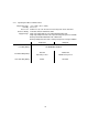
Table 6-6 Amount of Gear Oil Capacity Code Quarts Liters NER2 ER2 NER2 ER2 001H, 003S 0.55 0.72 0.52 0.68 005L 0.57 0.87 0.54 0.82 003H, 005S 0.57 0.95 0.54 0.90 010L, 020C 0.66 1.11 0.62 1.05 010S 0.72 1.16 0.68 1.10 015S, 020L 1.37 2.11 1.30 2.00 020S, 030C 2.01 2.64 1.90 2.50 025S, 030L, 050L 2.01 2.85 1.90 2.
4) Remove all chain components including the Bottom Hook Set Assembly, Stoppers, Cushion Rubbers, Chain Springs, Striker Plates, Chain Pin and End Wire (or End Suspender) from the chain for reuse on new chain. Inspect and replace any damaged or worn parts. 5) Using a C-link, attach the new chain to the end link of the old chain on the no-load side.
6.6.2 Mechanical Load Brake with Friction Clutch (ER2 Models) – If abnormal operation or slippage occurs do NOT attempt to disassemble or adjust the Mechanical Load Brake with Friction Clutch. Replace the worn or malfunctioning Mechanical Load Brake with Friction Clutch as an assembly with a new, factory adjusted part. 6.7 Storage 6.7.1 ER2 models with vented oil cap assemblies should be stored with the cap oriented up to prevent oil leakage. 6.7.2 The storage location should be clean and dry. 6.
7.0 Troubleshooting HAZARDOUS VOLTAGES ARE PRESENT IN THE HOIST AND IN CONNECTIONS BETWEEN COMPONENTS. Before performing ANY maintenance on the equipment, de-energize the supply of electricity to the equipment, and lock and tag the supply device in the de-energized position. Refer to ANSI Z244.1, “Personnel Protection – Lockout/Tagout of Energy Sources.
Table 7-1 Troubleshooting Guide Symptom Hoist will not operate (continued) Hoist lifts but will not lower Hoist lowers but will not lift Cause Remedy Faulty magnetic contactor Check coil for open or short circuit. Check all connections in the control circuit. Check for open contactors. Replace as needed. Faulty VFD (dual speed only) Check fault codes (Reference Section 3.6). Reset VFD by pressing the Emergency Stop Button on pendant. Replace as needed.
Table 7-1 Troubleshooting Guide Symptom Hoist will not lift rated load or does not have the proper lifting speed Load drifts excessively when hoist is stopped Motor or brake overheating Hoist operates intermittently Cause Remedy Hoist overloaded Reduce load to within rated capacity. Low voltage in hoist's power supply Determine cause of low voltage and bring to within plus or minus 10% of voltage specified on the motor nameplate. The voltage should be measured at the hoist contactor.
8.0 Warranty Warranty explanation and terms. All products sold by Harrington Hoists, Inc.
9.0 Parts List When ordering Parts, please provide the Hoist code number, lot number and serial number located on the Hoist nameplate (see fig. below). Reminder: Per sections 1.1 and 3.7.4 to aid in ordering Parts and Product Support, record the Hoist code number, lot number and serial number in the space provided on the cover of this manual. ER2/NER2 Series Nameplate The parts list is arranged into the following sections: Section Page 9.1 Housing and Motor Parts……………………………………………….………………………………………………..
9.
9.1 Housing and Motor Parts Figure No.
9.
9.1 Housing and Motor Parts Figure No.
9.
9.2 Gearing Parts Figure No.
9.
9.2 Gearing Parts Figure No.
9.
9.3 Hook and Chain Parts Figure No.
9.
9.3 Hook and Chain Parts Figure No.
9.
9.3 Hook and Chain Parts Figure No.
9.
9.
9.
9.
9.
9.
9.
9.3 Hook and Chain Parts Figure No. 1 2 3 4 5 6 7 8 9 10 11 12 13 14 15 16 17 18 19 20 21 22 23 24 25 26 Part Name Parts Per Hoist 025S Chain Guide A Chain Guide B Socket Bolt Spring Lock Washer Machine Screw With Spring Washer Guide Roller Roller Pin Limit Lever Limit Lever Pin Limit Lever Spring Limiting Plate Chain Spring Cushion Rubber Stopper Assembly Canvas Chain Container Assembly (Max.
9.
9.
9.
9.3 Hook and Chain Parts Figure No. 1 2 3 4 5 6 7 8 9 10 11 12 13 14 15 16 17 18 19 20 21 22 23 Part Name Chain Guide A Chain Guide B Socket Bolt Spring Lock Washer Machine Screw With Spring Washer Guide Roller Roller Pin Limit Lever Limit Lever Pin Limit Lever Spring Cushion Rubber Stopper Assembly Limiting Plate Chain Spring Canvas Chain Container Assembly (Max.
9.
9.4 Electric Parts (Single Speed) Figure No.
9.
9.4 Electric Parts (Single Speed) Figure No.
9.
9.4 Electric Parts (Single Speed) Figure No.
9.
9.5 Electric Parts (Dual Speed) Figure No.
9.
9.5 Electric Parts (Dual Speed) Figure No.
9.
9.5 Electric Parts (Dual Speed) Figure No.
9.
9.6 Power Supply and Pendant Parts Figure No. 1 2 3 4 Part Name Cord Support (Wire Stop) Mach. Screw W/Spring Washer Socket Frame Complete Assembly Socket Frame 5 Socket 4P Assembly 6 Tapping Flat Head Mach.
9.
9.6 Power Supply and Pendant Parts Figure No. 1 2 3 4 5 6 7 8 9 10 11 12 13 14 15 16 18 19 20 21 Part Name Cord Support (Wire Stop) Mach. Screw W/ Spring Washer Socket Frame Complete Assembly Socket Frame Holder C Tapping Flat Head Mach. Screw Mach. Screw W/ Spring Washer Mach. Screw W/Spring Washer Socket Frame Packing Holder Packing Power Supply Cable 4C Assembly Power Supply Cable 4C Cable Support Arm Cable Sup. 12 Assembly Cable Sup.
This Page Intentionally Left Blank 94
This Page Intentionally Left Blank 95
www.harringtonhoists.com Harrington Hoists, Inc. 401 West End Avenue Manheim, PA 17545-1703 Phone: 717-665-2000 Toll Free: 800-233-3010 Fax: 717-665-2861 Harrington Hoists – Western Division 2341 Pomona Rd.