EFFECTIVE: February 6, 2014 MOTORIZED TROLLEY MR2 SERIES 1 Ton through 20 Ton Capacity Code, Lot and Serial Number This equipment should not be installed, operated or maintained by any person who has not read and understood all the contents of this manual. Failure to read and comply with the contents of this manual can result in serious bodily injury or death, and/or property damage.
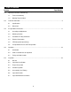
Table of Contents Section 1.0 2.0 3.0 4.0 5.0 Page Number Important Information and Warnings………………………………………………………………………. 4 1.1 Terms and Summary 1.2 Warning Tag and Labels Technical Information ………………………………………………………………………………………. 8 2.1 Specifications 2.2 Dimensions Pre-operational Procedures..……………………………………………………………………………... 11 3.1 Assembly and Adjustment 3.2 Mounting Location 3.3 Installation of Trolley onto Beam 3.4 Electrical Connections 3.5 VFD Setup (Dual Speed Only) 3.
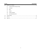
Section 6.0 Page Number Maintenance & Handling…………………………………………………………………………………...44 6.1 Count/Hour Meter (Dual Speed Only) 6.2 Lubrication 6.3 Brake 6.4 Storage 6.5 Outdoor Installation 6.6 Operational Environment 7.0 Troubleshooting……………………………………………………………………………………………. 47 8.0 Warranty……………………………………………………………………………………………………. 49 9.0 Parts List…………………………………………………………………………………………………….
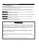
1.0 Important Information and Warnings 1.1 Terms and Summary This manual provides important information for personnel involved with the installation, operation and maintenance of this product. Although you may be familiar with this or similar equipment, it is strongly recommended that you read this manual before installing, operating or maintaining the product. Danger, Warning, Caution and Notice - Throughout this manual there are steps and procedures that can present hazardous situations.
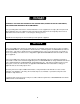
Equipment described herein is not designed for and MUST NOT be used for lifting, supporting, or transporting people, or for lifting or supporting loads over people. Equipment described herein should not be used in conjunction with other equipment unless necessary and/or required safety devices applicable to the system, crane, or application are installed by the system designer, system manufacturer, crane manufacturer, installer, or user.
HAZARDOUS VOLTAGES ARE PRESENT IN THE CONTROL BOX, OTHER ELECTRICAL COMPONENTS, AND CONNECTIONS BETWEEN THESE COMPONENTS. Before performing ANY mechanical or electrical maintenance on the equipment, de-energize (disconnect) the main switch supplying power to the equipment; and lock and tag the main switch in the de-energized position. Refer to ANSI Z244.1, “Personnel Protection – Lockout/Tagout of Energy Sources”. Only trained and competent personnel should inspect and repair this equipment.
1.2 Warning Tag and Labels The warning tag illustrated below in Figure 1-1 is supplied with each trolley shipped from the factory. If the tag is not attached to the pendant cord for your hoist/trolley, order a tag from your dealer and install it. Read and obey all warnings attached to this trolley. Tag is not shown actual size.
2.0 Technical Information 2.1 Specifications Note: This Owner’s Manual is to be used with the Enhanced Features Model ER and NER. The Enhanced Features Model is referred to as the ER2 and NER2 in this Owner’s Manual. Pendants are shown with optional Emergency Stop button. 2.1.1 Product Code for MR Trolley Alone: 2.1.
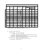
Table 2-1 Trolley Specifications Capacity (Ton) Product Code Standard Beam Flange Range (in) SINGLE SPEED (in) DUAL SPEED Optional Beam Flange Range Min. Allowable Radius for Curve (in) 1 MR2010L/S 2.28 to 5.00 2 MR2020L/S 3.23 to 6.02 3 MR2030L/S 3.23 to 6.02 5 MR2050L/S 3.94 to 7.01 8 MR2080L 5.50 to 8.66 10 MR2100L 15 5.01 to 6.02 OR Motor*** Output (Hp) Current Draw (amps) 208V or 460V 230V Approx. Net Weight (lbs) 31.5* 0.54 3.2 1.6 68 31.5** 0.54 3.2 1.
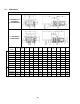
2.2 Dimensions Table 2-2 Trolley Dimensions For ER2/NER2001 to ER2/NER2020 (inc.ER2/NER2030C) Dual Speed Single Speed For ER2/NER2025 and ER2/NER2050 Product Code b b' d e e' i j k m n r t MR2010L/S 12.4 15.6 8.7 20.3 7.1 3.74 0.9 5.1 8.1 4.3 2.0 1.22 MR2020L/S 12.8 16.4 8.9 20.5 7.2 4.33 1.1 4.9 8.4 4.7 2.4 1.42 MR2030L/S 13.4 17.4 8.9 20.5 7.3 4.92 1.1 5.2 8.5 5.2 2.7 1.69 MR2050L/S 15.8 19.8 11.1 20.8 7.6 5.51 1.7 5.7 9.2 5.9 3.4 2.
3.0 Pre-operational Procedures 3.1 Assembly and Adjustment 3.1.1 When the MR2 trolley is combined with a hoist, follow and complete all pre-operational procedures provided with the hoist. For Harrington ER2 and NER2 model hoists, follow the pre-operational procedures in the ER2/NER2 Owner's Manual in conjunction with all information provided in this section for mounting and electrical connections. 3.1.
Figure 3-1 Installing Suspender T or Connection Yoke on ER2/NER2 Hoists – Up Through 3 Ton (030C) Capacity Figure 3-2 Oil Fill Cap placement on ER2 hoist.
2 ½ Ton and 3 Ton (030L) ER2/NER 2– The standard suspension configuration uses Suspender T which orients the hoist perpendicular to the trolley beam. Optional two-piece suspension method uses a Connection Yoke and Suspender G, which orients the hoist parallel to the trolley beam. If the hoist is not equipped with Suspender T or the Connection Yoke from the factory, remove the Top Hook Assembly from the hoist and install Suspender T or the Connection Yoke as follows in step 1).
Figure 3-3 Installing Suspender T or Connection Yoke on ER2/NER2 Hoists – 2½, 3 Ton (except 030C) and 5 Ton Capacity Note: Unlike 3 Ton (Single Fall) and below (see Figure 3-1), Suspender G for 2 Ton (020C), 3 Ton (030C) and 5 Ton connects directly to the Connection Yoke without the Connection Yoke Rubber.
3.1.5 Trolley Assembly 1) Refer to Figure 3-5 or 3-6. 2) Remove the Shaft Stopper Pin, Side Plate S, and Spacers from the Suspension Shaft. For beam flanges that are wider than the standard range, different suspension shaft and/or spacer arrangements are provided. Refer to Table 3-1. 3) Insert the Suspension Shaft to Side Plate G and attach it with the Suspension Shaft Bolt, Slotted Nut and Split Pin (cotter pin). Refer to Figure 3-7 and insure that correct Suspension Shaft holes are used.
Note: 15 and 20 Ton trolleys use 2 Suspension Shafts and do not use Trolley Fixing Shafts. Trolley Fixing Shaft is shown in front of Suspension Shaft for clarity. Actual location is behind the Suspension Shaft.
3.1.6 Adjusting the trolley width - After assembling trolley per Section 3.1.5, check the adjustment as follows: 1) Refer to Figure 3-8 or 3-9. 2) Make sure both side plates are spread fully outward and Measure Dimension "A". Compare dimension "A" with the following values: For trolleys up through 5 Ton, "A" must be 1/8 to 3/16" greater than "B". For trolleys 8 Ton and larger, "A" must be 7/32 to 9/32" greater than "B".
Note: Inner Spacer rows on Table 3-2 list two numbers. First number is the quantity of spacers located on the left side of the Suspender or Suspension Plates, second number is the quantity on the right side.
Table 3-2 Number of Adjusting Spacers Beam Flange Width (in) Cap.
Table 3-2 Number of Adjusting Spacers (continued) Beam Flange Width (in) Cap.
3.1.7 Counter Weight – For proper balance 1 Ton, dual speed MR2 trolleys (code MR2010SD) require a Counter Weight when installed on a 3 7/8 inch or smaller beam flange. The Counter Weight mounts on the Suspension Shaft as shown in Figure 3-11 and is held in place with a Bolt, Slotted Nut and Split Pin. The bolt is installed through holes B and C. Make sure the weight is securely fastened to the shaft and that the split pin is properly bent. All other trolley capacities do NOT require a counter weight.
Figure 3-12 Optional trolley installation method – up to 5 Ton 3.3.4 Optional Method for 8 to 20 Ton Trolley with hoist - refer to Figure 3-13. ALWAYS install the trolley onto the beam before installing the hoist to the trolley. Attempting to install a pre-assembled hoist and trolley onto the beam other than onto the beam end (per Section 3.3.2) is dangerous and must not be attempted. 1) Assemble and adjust the trolley.
Figure 3-13 Optional trolley installation method – 8 Ton and Larger 3.4 Electrical Connections 3.4.1 3.4.2 3.4.3 Ensure that the voltage of the electric power supply is proper for the hoist or trolley. Do NOT apply electronic soft-start control or voltage varying controls to the MR2 trolley. Use of such devices may cause the motor brake and other electrical components to malfunction. Variable frequency drives MAY be used with single speed MR2 trolleys, contact Harrington Hoists, Inc.
3.4.7 The following instructions apply to installations where an ER2 or NER2 model electric hoist is installed on an MR2 trolley. In this case the hoist and trolley are controlled by a pendant with four push buttons – two for the hoist motion and two for the trolley motion. Special wiring considerations must be taken if the trolley is used with a hoist other than an ER2 or NER2 model. Pendant Cord - The Pendant Cord connects to the trolley via an 8-pin (8P) Plug and Socket.
3.4.8 Connection to Electrical Power Source - The red, blue and black wires of the Power Supply Cable should be connected to an Electric Power Disconnect Switch or Circuit Breaker. This connection should be made so that the ER2/NER2 or other hoist is phased properly. Refer to Section 3.6.5 for instructions on how to check for correct power supply phase connection. 3.4.
Figure 3-15 Pendant and Power Supply Cable Connection - Product Code ER2/NER2M100S to ER2/NER2M200S Single Speed Trolley Dual Speed Trolley Figure 3-16 Power supply cable terminal connections.
Figure 3-17 Power Supply Cable installation and Guide Wire location.
3.5 VFD Setup (Dual Speed Only) 3.5.1 To avoid a shock hazard, DO NOT perform ANY mechanical or electrical maintenance on the dual speed (or VFD control) trolley or hoist within 5 minutes of de-energizing (disconnecting) the trolley or hoist. This time allows the internal VFD capacitor to safely discharge. 3.5.2 Do Not remove power to the hoist or trolley during operation. 3.5.3 All dual speed trolleys are equiped with a VFD.
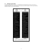
3.5.6 During operation the data display will exhibit illuminating or blinking data as shown in Figure 3-9. Figure 3-9 Illuminating/Blinking Display 3.5.7 The digital display uses a seven segment character to form the specific charaters used in the display. Table 3-4 shows the corresponding digital characters to its English eqivalent.
3.5.9 The Run Lamp display provides trolley “RUN” status. Table 3-6 shows the various “RUN” displays. Table 3-6 Run Lamp 3.5.10 All of the dual speed trolleys have speed/frequency ranges that can be customized to a specific application. Refer to Table 3-7 for specific trolley speed/frequency ranges. To set custom speeds for an application, follow the procedure in Table 3-8.
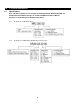
Table 3-8 Dual Speed Trolley (w/VFD) Speed/Frequency Change Procedure Each dual speed trolley has a range of available speeds/frequencies (upper and lower limits). Any value outside the range listed in Table 3-7 for your specific trolley is strictly prohibited. Speeds must be set such as Low [d1-01] and High [d1-02]. After parameters are changed, a “no load” operational check must be performed. Operational Step VFD Display 1. Energize the trolley. 2.
Table 3-10 Trolley VFD 2-Step/3-Step Infinitely Variable Parameter Setup Procedure Each dual speed trolley model has a range of available speeds/frequencies (upper and lower limits) and acceleration/deceleration time parameters. Refer to Owner’s Manual MOTORIZED TROLLEY MR2 SERIES. Any value outside the range listed in Table 3-7 for your specific trolley is strictly prohibited. Speeds must be set such as Low [d1-01] and High [d1-02].
3.6 Pre-operational Checks and Trial Operation 3.6.1 Refer to the trolley's Nameplate and record the Code, Lot and Serial Number in the space provided on the cover of this manual. 3.6.2 Refer to the hoist's owner's manual and perform all pre-operational checks for the hoist. 3.6.3 Perform pre-operational checks for the trolley: Confirm the adequacy of the rated capacity for all slings, chains, wire ropes and all other lifting attachments before use.
4.0 Operation 4.1 Introduction DO NOT WALK UNDER A SUSPENDED LOAD HOIST OPERATORS SHALL BE REQUIRED TO READ THE OPERATION SECTION OF THIS MANUAL, THE WARNINGS CONTAINED IN THIS MANUAL, INSTRUCTION AND WARNING LABELS ON THE HOIST OR LIFTING SYSTEM, AND THE OPERATION SECTIONS OF ANSI/ASME B30.16 and ANSI/ASME B30.10. THE OPERATOR SHALL ALSO BE REQUIRED TO BE FAMILIAR WITH THE HOIST AND HOIST CONTROLS BEFORE BEING AUTHORIZED TO OPERATE THE HOIST OR LIFTING SYSTEM.
The operation of an overhead hoist involves more than activating the hoist’s controls. Per the ANSI/ASME B30 standards, the use of an overhead hoist is subject to certain hazards that cannot be mitigated by engineered features, but only by the exercise of intelligence, care, common sense, and experience in anticipating the effects and results of activating the hoist’s controls.
Improper operation of a hoist can create a potentially hazardous situation which, if not avoided, could result in minor or moderate injury, or property damage. To avoid such a potentially hazardous situation THE OPERATOR SHALL: • Maintain a firm footing or be otherwise secured when operating the hoist. • Use the hoist manufacturer’s recommended parts when repairing the unit. • Check brake function by tensioning the hoist prior to each lift operation.
4.3 Trolley and Hoist Controls 4.3.1 Emergency Stop Button – Press the Emergency Stop Button to perform an emergency stop and lockout of hoist motion controls or to reset the VFD as shown in Figure 4-1. Turn the Emergency Stop Button clockwise to unlock the controls and allow hoist operation. “Hbb” will appear on the dual speed unit’s VFD display when the Emergency Stop Button is depressed. 4.3.
5.0 Inspection 5.1 General 5.1.1 5.2 The inspection procedure herein is based on ANSI/ASME B30.16. The following definitions are from ANSI/ASME B30.16 and pertain to the inspection procedure below. Designated Person - a person selected or assigned as being competent to perform the specific duties to which he/she is assigned.
5.3 Frequent Inspection 5.3.1 Inspections should be made on a FREQUENT basis in accordance with Table 5-1, “Frequent Inspection.” Included in these FREQUENT Inspections are observations made during operation for any defects or damage that might appear between Periodic Inspections. Evaluation and resolution of the results of FREQUENT Inspections shall be made by a designated person such that the trolley is maintained in safe working condition.
5.7 Inspection Methods and Criteria 5.7.1 This section covers the inspection of specific items. The list of items in this section is based on those listed in ANSI/ASME B30.16 for Frequent and Periodic Inspection. In accordance with ANSI/ASME B30.16, these inspections are not intended to involve disassembly of the trolley. Rather, disassembly for further inspection would be required if frequent or periodic inspection results so indicate.
Table 5-3 Trolley Inspection Methods and Criteria Item Method Criteria Action Pendant - Switches Function Depressing and releasing push buttons should make and break contacts in switch contact block and result in corresponding electrical continuity or open circuit. Push-buttons should be interlocked either mechanically or electrically to prevent simultaneous energization of circuits for opposing motions (e.g. forward and reverse). Repair or replace as necessary.
Table 5-4 Track Wheel Wear Dimensions 1 to 5 Ton: 8 to 20 Ton: Note: Track wheels are for flat and tapered flanges. “d” Dimension inch (mm) Capacity (Ton) “D” Dimension inch (mm) Standard Discard Standard Discard 1 3.60 (91.5) 3.44 (87.5) 3.74 (95) 3.58 (91) 2 4.17 (106) 3.98 (101) 4.33 (110) 4.13 (105) 3 4.76 (121) 4.49 (114) 4.92 (125) 4.65 (118) 5 5.31 (135) 5.00 (127) 5.51 (140) 5.20 (132) 8 to 20 6.34 (166) 6.14 (156) 6.89 (175) 6.
Table 5-6 Motor Brake Wear Dimensions "A" Dimension - inch (mm) Capacity (Ton) Single Speed Dual Speed Standard Discard Standard Discard 1 and 2 1.28 (32.5) 1.22 (31.0) 1.45 (36.8) 1.43 (36.3) 3 to 20 1.28 (32.5) 1.22 (31.0) 1.45 (36.8) 1.41 (35.
6.0 Maintenance & Handling 6.1 Count/Hour Meter (Dual Speed Only) 6.1.1 Dual Speed On dual speed trolleys, the VFD has a Count/Hour function built into the parameters. Refer to Table 6-1 for parameter identification. Refer to Table 6-2 for Count/Hour access procedure. Table 6-1 VFD Count/Hour Parameter Identification Parameter Name U7-01 Number of Starts (Higher Order) Discription The number of starts in the down direction x 1,000. Up to 10,000 units are displayed. Display of “1” = 1,000 starts.
6.2 6.3 6.1.2 Gear Lubricant – The Dual Speed Trolley C/H Meter can be used in conjunction with the average operation of the trolley to estimate when the gear lubricant should be changed. Refer to Section 6.2.3. 6.1.3 You are encouraged to use the Dual Speed Trolley Count/Hour Meter in conjunction with your experience with the trolley's application and usage to develop a history upon which to gage and fine tune your maintenance program for the trolley. Lubrication 6.2.
6.5 6.6 Outdoor Installation 6.5.1 For trolley installations that are outdoors, the trolley MUST BE covered and protected from the weather at all times. 6.5.2 Possibility of corrosion on components of the trolley increases for installations where salt air and high humidity are present. The trolley may require more frequent lubrication. Make frequent and regular inspections of the unit's condition and operation. 6.5.
7.0 Troubleshooting HAZARDOUS VOLTAGES ARE PRESENT IN THE TROLLEY AND IN CONNECTIONS BETWEEN COMPONENTS. Before performing ANY maintenance on the equipment, de-energize the supply of electricity to the equipment, and lock and tag the supply device in the de-energized position. Refer to ANSI Z244.1, “Personnel Protection – Lockout/Tagout of Energy Sources.
Table 7-1 Troubleshooting Guide Symptom Trolley drifts excessively when stopping Motor or brake overheating Trolley operates intermittently Cause Motor brake not holding Remedy Clean and inspect brake lining. Replace if necessary VFD Deceleration parameter adjusted incorrectly (Dual Speed only) Readjust VFD Deceleration parameter (Reference Section 3.5.11). Excessive duty cycle Reduce frequency of trolley movement.
8.0 Warranty All products sold by Harrington Hoists, Inc.
This Page Intentionally Left Blank 50
9.0 Parts List When ordering parts, please provide the trolley code number, lot number and serial number located on the hoist name Plate (see fig. below). Reminder: Per sections 1.1 and 3.6.1 to aid in ordering parts and product Support, record the trolley code number, lot number and serial number in the space provided on the Cover of this manual. MR2 Series Name Plate The parts list is arranged into the following sections: Section 1/8 to 5 Ton 9.1 9.2 9.3 9.4 9.
9.
9.1 Electric Parts– 1/8 to 5 Ton (Single Speed) Figure No.
9.
9.1 Electric Parts– 1/8 to 5 Ton (Dual Speed) Figure No.
9.
9.1 Electric Parts– 1/8 to 5 Ton (Direct Connection) 2 Holder A Parts Per Trolley 1 3 Holder B 3 ECP5924AB 4 5 8 9 10 26 27 28 29 30 31 32 Packing Holder Nut Plate D Cord Cover Packing Machine Screw With Spring Washer Power Supply Cable Assembly Holder A Holder B Packing Holder Nut Cable Packing S.O.
9.
9.2 Pendant Parts – 1/8 to 5 Ton Figure No.
9.
9.3 Power Supply Parts – 1/8 to 5 Ton Figure No.
9.
9.4 Side Plates and Suspension Parts– 1/8 to 5 Ton Figure No.
9.
9.
9.
9.6 Motor Parts – 8 to 20 Ton Figure No.
9.
9.7 Side Plates and Suspension Parts – 8 to 20 Ton Figure No.
9.
9.8 Electric Parts – 8 to 20 Ton Figure No.
9.
9.9 Pendant Parts – 8 to 20 Ton Figure No.
9.
9.10 Optional Parts – 8 to 20 Ton Figure No.
www.harringtonhoists.com Harrington Hoists, Inc. 401 West End Avenue Manheim, PA 17545-1703 Phone: 717-665-2000 Toll Free: 800-233-3010 Fax: 717-665-2861 Harrington Hoists – Western Division 2341 Pomona Rd.