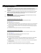
EFFECTIVE: April 24, 2003 Owner’s Manual MOTORIZED AIR TROLLEY MCR SERIES ¼ Ton through 6 Ton Capacity Code and Serial Number WARNING This equipment should not be installed, operated or maintained by any person who has not read and understood all the contents of this manual. Failure to read and comply with the contents of this manual can result in serious bodily injury or death, and/or property damage.
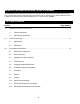
IMPORTANT INFORMATION ON HOW TO USE THIS MANUAL This OWNER’S MANUAL is intended for the MCR Air Trolley used with the TCR Air Hoist as a TCRM model Air Trolley Hoist. No other hoist and trolley combinations are covered in this manual. References to the “Owner’s Manual for the Air Powered Chain Hoist TCR Series” will be designated by the use of the acronym “TCROM”. 1.0 Table of Contents Section 1.0 2.0 3.0 Page Number Important Information and Warnings………………………………………………………………………. 4 1.
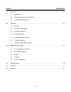
Section 4.0 5.0 6.0 Page Number Operation…………………………………………………………………………………………………… 27 4.1 Introduction 4.2 Shall’s and Shall Not’s for Operation 4.3 Trolley and Hoist Controls Inspection……………………………………………………………………………………………………30 5.1 General 5.2 Inspection Classification 5.3 Frequent Inspection 5.4 Periodic Inspection 5.5 Occasionally Used Trolleys 5.6 Inspection Records 5.7 Inspection Methods and Criteria Maintenance & Handling…………………………………………………………………………………...36 6.
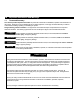
1.0 Important Information and Warnings 1.1 Terms and Summary This manual provides important information for personnel involved with the installation, operation and maintenance of this product. Although you may be familiar with this or similar equipment, it is strongly recommended that you read this manual before installing, operating or maintaining the product. Danger, Warning, Caution and Notice - Throughout this manual there are steps and procedures that can present hazardous situations.
WARNING Equipment described herein is not designed for and MUST NOT be used for lifting, supporting, or transporting people, or for lifting or supporting loads over people. Equipment described herein should not be used in conjunction with other equipment unless necessary and/or required safety devices applicable to the system, crane, or application are installed by the system designer, system manufacturer, crane manufacturer, installer, or user.
DANGER HAZARDOUS AIR PRESSURE IS PRESENT IN THE HOIST, IN THE SUPPLY OF COMPRESSED AIR TO THE HOIST, AND IN THE CONNECTIONS BETWEEN COMPONENTS. Before performing ANY maintenance on the equipment, de-energize the supply of compressed air to the equipment, and lock and tag the supply device in the de-energized position. Refer to ANSI Z244.1, “Personnel Protection - Lockout/Tagout of Energy Sources.” Only trained and competent personnel should inspect and repair this equipment.
1.2 Warning Tag and Labels The warning tag illustrated below in Figure 1-1 is supplied with each trolley shipped from the factory. If the tag is not attached to the pendant cord for your hoist/trolley, order a tag from your dealer and install it. Read and obey all warnings attached to this trolley. Tag is not shown actual size.
2.0 Technical Information 2.1 Specifications 2.1.1 Product Code for MCR Trolley Alone: 2.1.2 Product Code for MCR Air Trolley with TCR Series Air Hoist: Table 2-1 Trolley Hoist Specifications Cap. (Tons) MCR Product Code TCRM Product Code 1/4 TCRM250P 1/2 TCRM500P 1 MCR1000 Push Standard Button Cord Lift L (ft) (ft) TCRM1000P2 10 7.4 TCR Lifting/Lowering Speeds (ft/min) 90 psi Lifting / Lowering No Load w/Rated Load 68 / 44 37 / 57 34 / 22 18.5 / 28.
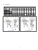
2.2 Dimensions Table 2-2 Trolley Hoist Dimensions Cap. (Tons) Headroom C (in) Product Code 1/4 TCRM250P 1/2 TCRM500P b (in) b' (in) d (in) e (in) e' (in) 12.4 15.6 10.3 6.2 3.7 13.4 17.4 10.5 6.9 3.9 15.7 19.8 10.8 8.1 4.3 g (in) i (in) j (in) k (in) m (in) n (in) r (in) t (in) 3.7 0.9 4.8 4.6 4.4 2.1 1.2 5.0 5.1 5.5 2.9 1.7 5.5 5.7 6.1 3.6 2.3 19.3 1 TCRM1000P2 21.5 1 TCRM1000P 19.5 2 TCRM2000P2 22.2 3 TCRM3000P 21.8 6 TCRM6000P2 25.
3.0 Pre-operational Procedures 3.1 Assembly and Adjustment 3.1.1 When the MCR trolley is combined with a hoist, follow and complete all pre-operational procedures provided with the hoist. For Harrington TCR model hoists, follow the pre-operational procedures in the TCR Owner's Manual in conjunction with all information provided in this section for mounting and air hose connections. 3.1.
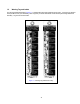
Figure 3-1 Installing Suspender on single fall hoists TCR250P, 500P, 1000P and 3000P 3.1.5 Figure 3-2 Installing suspender on double fall hoists TCR1000P2, 2000P2 and 6000P2 Trolley Assembly 1) Refer to Figure 3-3. 2) Remove the Shaft Stopper Pin, Side Plate S (counterweight side), and Spacers from the Suspension Shaft. Refer to Table 3-1. 3) Insert the Suspension Shaft to Side Plate G (motor side) and attach it with the Suspension Shaft Bolt, Slotted Nut and Split Pin (cotter pin).
Figure 3-3 Assembling the Trolley Table 3-1 Suspension Shaft Adjusting Spacers, and Suspension Shaft Bolt Total Number of Spacers Supplied Product Code Flange Range (in) Thin Thick Suspension Shaft Bolt Location MCR1000 2.28 to 5.00 8 5 Hole 2 MCR3000 3.94 to 6.02 8 3 Hole 2 MCR6000 4.92 to 7.
Figure 3-4 Suspension Shafts Note: Inner Spacer rows on Table 3-2 list two numbers. First number is the quantity of spacers located on the left side of the Suspender or Suspension Plates, second number is the quantity on the right side.
3.1.6 Adjusting the trolley width - After assembling trolley per Section 3.1.5, check the adjustment as follows: 1) Refer to Figure 3-6. 2) Make sure both side plates are spread fully outward and Measure Dimension "A". Compare dimension "A" with the following values: For MCR1000 trolleys, "A" must be 1/8 to 3/16" greater than "B". For MCR3000 and MCR6000, "A" must be 7/32 to 9/32" greater than "B".
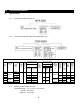
Table 3-2 Number of Adjusting Spacers Beam Flange Width 2 12 MCR1000 Thin Thick 15 MCR3000 Thin Thick MCR6000 Thin Thick 3 (in) 25 Prod Spacer Code Type (mm) 8 Inner 4 66 74 76 4+4 1+0 1+2 0 7 5 0+0 1+1 5 3 5 16 37 8 3 15 16 4 43 16 45 16 47 82 90 98 100 102 106 110 113 2+3 0 1+0 1+0 1+1 2+2 2+3 3 8 7 7 5 4 3 1+1 1+1 2+2 2+2 2+2 2+2 2+2 3 3 1 1 1 1 1 0 1+0 1+1 1+2 91 5 78 4 15 16 16 75 3 39 43 73 Inner 0+0 Outer 2 15 3
3.1.7 Attaching the Hangar Bracket and Hangar. For MCR1000 and MCR3000 Trolleys 1) Refer to Figure 3-7. 2) Attach the Hangar Bracket to the Side Plate with the hardware provided. 3) Attach the Hangar to the Hangar Bracket with the hardware provided. 4) Attach the Hangar to the hoist with the hardware provided. For MCR6000 Trolley 1) Refer to Figure 3-7. 5) Attach the Hangar to the hoist with the hardware provided.
Figure 3-7 Hangar Bracket and Bracket Attachment 17
3.2 Mounting Location 3.2.1 3.2.2 3.3 WARNING Prior to mounting the trolley (and hoist) ensure that the trolley beam and its supporting structure are adequate to support the trolley, hoist and its loads. If necessary consult a professional that is qualified to evaluate the adequacy of the suspension location and its supporting structure. NOTICE See Section 6.4 for outdoor installation considerations. Installation of Trolley onto Beam 3.3.
3.4 Air Connections 3.4.1 3.4.2 3.4.3 CAUTION Ensure that the air supply pressure and volume is proper for the hoist or trolley. DANGER Before proceeding, ensure that the air supply for the hoist or trolley has been deenergized (disconnected). Lock out and tag out in accordance with ANSI Z244.1 “Personnel Protection -Lockout/Tagout of Energy Sources”. This instruction applies to installations where a TCR model air hoist is installed on an MCR trolley.
Figure 3-9 Air Supply and Pendant Hose Connections 20
3.5 Air Supply System Requirements 3.5.1 NOTICE Pressure and Flow - Verify that the air supply system has capacity to supply your air trolley hoist with required pressure and flow. Otherwise the hoist may operate poorly or may fail to operate. See Section 3.6. 3.5.2 CAUTION Lubrication - The trolley hoist requires lubrication for proper operation. The oil in the air supply is the primary source of lubrication to the hoist. Therefore, a dedicated air supply lubricator must be used with the trolley hoist.
3.8 Filtration 3.8.1 CAUTION The air entering the trolley inlet must not contain any particulate greater than 5 microns in size. Therefore, the hoist must have a 5 micron filter in its air supply. The filter must be upstream of the lubricator. 3.8.2 The filter servicing the trolley hoist can also service other hoists and air consuming equipment. In this case, the air filter must be in sized for the total air consumption of the equipment it is servicing.
Figure 3-11 Typical Air Supply Filter, Regulator and Lubricator. 3.10.2 NOTICE Piping - Pipe should be sized to accommodate the trolley hoist airflow requirements. Table 3-3 gives recommended pipe sizes. Table 3-3 Air Supply Pipe and Hose Sizes Diameter of Supply Pipe Diameter of Supply Hose TCRM250P, 500P, 1000P, 1000P2, 2000P2 Inside diameter 0.75 inch or larger Inside diameter 0.5 inch or larger TCRM3000P, 6000P2 Inside diameter 1.0 inch or larger Inside diameter 0.75 inch or larger Model 3.
Figure 3-12 Typical Arrangements of Filter, Regulator and Lubricator and Maximum Air Supply Hose Lengths 3.10.4 CAUTION Fittings - Important considerations regarding fittings in the hoist and trolley's air supply include: When connecting air supply components, remove all dirt or debris from the connecting surfaces of the hoses, pipes, fittings, or threaded fasteners to prevent contaminants from entering the hoist and trolley.
3.11.6 NOTICE Where conditions dictate, the installation sequence can be reversed by connecting the air supply first, followed by mounting the trolley hoist. Figure 3-13 Typical Air Supply Connection 3.12 Pre-operational Checks and Trial Operation 3.12.1 Refer to the trolley's Nameplate and record the Code and Serial Number in the space provided on the cover of this manual. 3.12.2 Refer to the hoist's owner's manual and perform all pre-operational checks for the hoist. 3.12.
3.12.5 Proceed with trial operation to confirm proper operation. Verify that the controls agree with hoist direction. Make sure that depressing the Up button lifts the load chain and depressing the Down button lowers the load chain hook. If the load chain does not move in the correct direction when the push buttons are pushed, the air tubes are connected incorrectly. In this case, turn off the air supply and correct the pendant tube attachment at the hoist.
4.0 Operation 4.1 Introduction DANGER DO NOT WALK UNDER A SUSPENDED LOAD WARNING HOIST OPERATORS SHALL BE REQUIRED TO READ THE OPERATION SECTION OF THIS MANUAL, THE WARNINGS CONTAINED IN THIS MANUAL, INSTRUCTION AND WARNING LABELS ON THE HOIST OR LIFTING SYSTEM, AND THE OPERATION SECTIONS OF ANSI/ASME B30.16 and ANSI/ASME B30.10. THE OPERATOR SHALL ALSO BE REQUIRED TO BE FAMILIAR WITH THE HOIST AND HOIST CONTROLS BEFORE BEING AUTHORIZED TO OPERATE THE HOIST OR LIFTING SYSTEM.
The operation of an overhead hoist involves more than activating the hoist’s controls. Per the ANSI/ASME B30 standards, the use of an overhead hoist is subject to certain hazards that cannot be mitigated by engineered features, but only by the exercise of intelligence, care, common sense, and experience in anticipating the effects and results of activating the hoist’s controls.
CAUTION Improper operation of a hoist can create a potentially hazardous situation which, if not avoided, could result in minor or moderate injury, or property damage. To avoid such a potentially hazardous situation THE OPERATOR SHALL: • Maintain a firm footing or be otherwise secured when operating the hoist. • Use the hoist manufacturer’s recommended parts when repairing the unit. • Check brake function by tensioning the hoist prior to each lift operation.
5.0 Inspection 5.1 General 5.1.1 The inspection procedure herein is based on ANSI/ASME B30.16. The following definitions are from ANSI/ASME B30.16 and pertain to the inspection procedure below. Designated Person - a person selected or assigned as being competent to perform the specific duties to which he/she is assigned.
5.3 Frequent Inspection 5.3.1 Inspections should be made on a FREQUENT basis in accordance with Table 5-1, “Frequent Inspection.” Included in these FREQUENT Inspections are observations made during operation for any defects or damage that might appear between Periodic Inspections. Evaluation and resolution of the results of FREQUENT Inspections shall be made by a designated person such that the trolley is maintained in safe working condition.
5.6 Inspection Records 5.6.1 5.7 Dated inspection reports and records should be maintained at time intervals corresponding to those that apply for the hoist’s PERIODIC interval per Section 5.2.4. These records should be stored where they are available to personnel involved with the inspection, maintenance, or operation of the trolley. Inspection Methods and Criteria 5.7.1 This section covers the inspection of specific items. The list of items in this section is based on those listed in ANSI/ASME B30.
Table 5-3 Trolley Inspection Methods and Criteria Item Method Criteria Action Pendant – Tubing Visual Surface of tubing should be free from nicks, gouges, and abrasions. Tubing should not leak even when flexed back-and-forth. Tubing should not be deformed or loosely connected and free of significant deterioration. Replace Pendant – Buttons Function Depressing and releasing push buttons should start or stop load chain or trolley movement. Repair or replace as necessary.
Table 5-4 Track Wheel Wear Dimensions Note: Track wheels are for flat and tapered flanges. “d” Dimension inch (mm) Trolley Code “D” Dimension inch (mm) Standard Discard Standard Discard MCR1000 3.60 (91.5) 3.44 (87.5) 3.74 (95) 3.58 (91) MCR3000 4.76 (121) 4.49 (114) 4.92 (125) 4.65 (118) MCR6000 6.34 (166) 6.14 (156) 6.89 (175) 6.50 (165) Table 5-5 Side Roller Wear Dimensions Trolley Code “R” Dimension inch (mm) Standard Discard MCR1000 1.50 (38) 1.46 (37) MCR3000 1.
Table 5-6 Motor Brake Wear Dimensions "A" Dimension - inch (mm) Trolley Code Standard Discard 0 (0) 0.04(1.
6.0 Maintenance & Handling 6.1 Air Trolley Motor Lubrication 6.1.1 See Section 3.7 for lubrication requirements. 6.1.2 CAUTION Lubrication to the motor will be provided primarily by the air supply lubricator. The recommended amount is 10-15 drops/minute (2-3cc/min.). Refer to Table 6-1 below for the approved lubricant for use with your air hoist. 6.1.3 Additional lubrication to the reduction gears is not necessary.
6.4 6.5 6.1.8 Brake O-ring Inspection – The brake piston and brake cover o-rings should be free of nicks, cuts and breaks. 6.1.9 Motor Brake Installation - After the brake is inspected, carefully place the brake components into the Case. Be sure to reseal the Brake Cover to the Case surface using a small bead of liquid (hitemperature) sealant. Install the Brake Cover attachment bolts. Storage 6.4.1 The storage location should be clean and dry. 6.4.
7.0 Troubleshooting WARNING HAZARDOUS AIR PRESSURE IS PRESENT IN THE HOIST, IN THE SUPPLY OF COMPRESSED AIR TO THE HOIST, AND IN THE CONNECTIONS BETWEEN COMPONENTS. Before performing ANY maintenance on the equipment, de-energize the supply of compressed air to the equipment, and lock and tag the supply device in the de-energized position. Refer to ANSI Z244.1, “Personnel Protection - Lockout/Tagout of Energy Sources.” Only trained and competent personnel should inspect and repair this equipment.
8.0 Warranty Warranty explanation and terms. All products sold by Harrington Hoists, Inc.
This Page Intentionally Left Blank 40
9.0 Parts List When ordering Parts, please provide the trolley's code number and serial number located on the trolley's nameplate (see figure 9-1 below). Reminder: Per sections 1.1 and 3.12.1 to aid in ordering Parts and Product Support, record the Trolley's code number and serial number in the space provided on the cover of this manual. Figure 9-1 MCR Nameplate The parts list is arranged into the following sections: Section Page 9.1 Side Plates, Gearbox and Suspension Parts………………………………...……….………….
9.1 Side Plates, Gearbox and Suspension Parts Figure 9-2 Side Plates, Gearbox and Suspension Components.
9.1 Side Plates, Gearbox and Suspension Parts Fig. No. Description Qty.
9.1 Side Plates, Gearbox and Suspension Parts Fig. No. 101 Description Qty.
9.
9.
9.2 Air Motor and Control Valve Parts Fig. No. Description Qty.
9.
9.3 Air Connection and Pendant Parts Fig. No. Description TCRM250P TCRM500P TCRM1000P2 TCRM1000P TCRM2000P2 Qty.
NOTES 50
NOTES 51
www.harringtonhoists.com Harrington Hoists, Inc. 401 West End Avenue Manheim, PA 17545-1703 Phone: 717-665-2000 Toll Free: 800-233-3010 Fax: 717-665-2861 Harrington Hoists – Western Division 2341 Pomona Rincon Rd.