EFFECTIVE: October 4, 2012 LEVER OPERATED CHAIN HOIST LB SERIES MODEL L5 3/4 Ton through 9 Ton Capacity Code, Lot and Serial Number This equipment should not be installed, operated or maintained by any person who has not read and understood all the contents of this manual. Failure to read and comply with the contents of this manual can result in serious bodily injury or death, and/or property damage.
Table of Contents Section 1.0 2.0 3.0 4.0 5.0 Page Number Important Information and Warnings ……………………………………………………………………… 4 1.1 Terms and Summary 1.2 Warning Tags and Labels Technical Information…………………………………………………………………………….…………. 7 2.1 Specifications 2.2 Dimensions 2.3 Optional Equipment Preoperational Procedures ……………………………………………………………………………… 12 3.1 Chain 3.2 Attachment Points 3.3 Mounting the Hoist 3.
Section 5.7 6.0 Page Number Inspection Methods and Criteria Maintenance & Handling …………………………………………………………………………………. 33 6.1 Lubrication 6.2 Disassembly, Assembly and Adjustment 6.3 Hoist Disassembly 6.4 Hoist Assembly 6.5 Storage 6.6 Outdoor Installation 7.0 Troubleshooting …………………………………………………………………………………………… 46 8.0 Warranty …………………………………………………………………………………………………… 51 9.
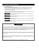
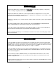
1.0 Important Information and Warnings 1.1 Terms and Summary This manual provides important information for personnel involved with the installation, operation and maintenance of this product. Although you may be familiar with this or similar equipment, it is strongly recommended that you read this manual before installing, operating or maintaining the product. Danger, Warning, Caution and Notice Throughout this manual there are steps and procedures that can present hazardous situations.
Equipment described herein is not designed for and MUST NOT be used for lifting, supporting, or transporting people, or for lifting or supporting loads over people. Equipment described herein should not be used in conjunction with other equipment unless necessary and/or required safety devices applicable to the system, crane, or application are installed by the system designer, system manufacturer, crane manufacturer, installer, or user.
1.2 Warning Tags and Labels The warning tag illustrated below in Figure 1-1 is supplied with each hoist shipped from the factory. If the tag is not attached to your hoist‟s no-load side of the load chain, order a tag from your dealer and install it. Read and obey all warnings attached to this hoist. Tag is not shown actual size.
2.0 Technical Information 2.1 Specifications 2.1.1 Product Code 2.1.2 Operating Conditions and Environment Temperature range: Humidity: -40° to +140°F (-40° to +60°C) 100% or less (Not an Underwater Device) Table 2-1 Hoist Specifications Cap. (Tons) Product Code ¾ LB008 Std. Lift (ft) Pull to Lift Load* (lbs) Load Chain Diameter (mm) x Chain Fall Lines Net Weight (lbs) 5.6 x 1 13 Shipping Weight Approx.
2.2 Dimensions Table 2-2 Hoist Dimensions Cap. Product a b (Tons) Code (in) (in) ¾ LB008 1 LB010 5.7 4.7 1½ LB015 6.3 5.0 2 LB020 2¾ LB028 3 LB030 6 LB060 9 LB090 6.8 7.5 Headroom C (in) 11.0 11.8 D* e f g (in) (in) (in) (in) 9.6 (14.4) 3.8 1.6 3.9 1.5 13.2 5.9 14.8 6.3 15.6 8.5 21.3 12.0 26.8 10.4 (14.4) 4.0 1.8 0.9 1.1 1.3 1.4 1.5 16.3 (16.9) 4.4 2.3 2.0 4.1 2.
Table 2-3 Hook Dimension* T = Top Hook B = Bottom Hook Units = inch Cap. (Tons) Product Code Hook ¾ LB008 T&B 1 LB010 T&B 1½ LB015 a b c d e g 0.9 0.6 0.8 0.6 1.4 0.93 1.7 1.14 T&B 1.2 0.7 1.0 0.7 1.7 1.26 T&B 1.4 0.8 1.14 0.8 1.9 1.44 2 LB020 2¾ LB028 3 LB030 T&B 1.6 1.0 1.2 1.0 2.0 1.54 6 LB060 T&B 2.1 1.3 1.6 1.3 2.4 1.97 9 LB090 T&B 2.6 1.6 2.0 1.6 3.4 2.85 *Refer to Section 5.7 for inspection dimensions and limits. 2.
Figure 2-2 Shipyard Hooks 2.3.3 Top Hook Extender The Top Hook Extender is designed to move the hoist body away from the attachment point. It can be used to place the hoist lower in vertical application or increase the hoist reach in horizontal applications. Refer to Figure 2-3. The Top Hook Extender Parts Kit contains a hook set, chain, top and bottom yokes, extension block and all necessary hardware. Kits are available for LB008 through LB030 hoists.
Figure 2-4 Latch Lock Hooks 2.3.5 Inspection Hooks The Inspection Hook is designed to facilitate the inspection of the internal surfaces of the hook yoke and shank portion of the hook itself. The Inspection Hook is suitable for applications where inspection of the internal parts of the hook set is required. The inspection hook uses the standard Harrington hook set and is assembled with high-strength locking fasteners instead of rivets. Inspection hooks are available in top and bottom versions.
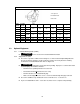
3.0 Preoperational Procedures 3.1 Chain 3.1.1 3.1.2 A chain stopper link must be installed on the second to last chain link on the noload end of the load chain. Verify that the load chain is not twisted or tangled prior to operating the hoist. Make sure the bottom hook on the 6 (LB060) and 9 (LB090) Ton multiple fall hoists is not capsized. See Figures 3-1 and 3-2. Correct all chain irregularities before conducting the first hoist operation.
3.2 Attachment Points 3.2.1 3.2.2 3.3 Prior to attaching the hoist ensure that all attachment points, suspension components and supporting structure are adequate to support the hoist and its load. If necessary consult a professional that is qualified to evaluate the adequacy of the suspension location and its supporting structure. See Section 6.6 for outdoor installation considerations. Mounting the Hoist 3.3.1 3.3.2 3.
4.0 Operation 4.1 Introduction DO NOT WALK UNDER A SUSPENDED LOAD HOIST OPERATORS SHALL BE REQUIRED TO READ THE OPERATION SECTION OF THIS MANUAL, THE WARNINGS CONTAINED IN THIS MANUAL, INSTRUCTION AND WARNING LABELS ON THE HOIST OR LIFTING SYSTEM, AND THE OPERATION SECTIONS OF ANSI/ASME B30.21 and ANSI/ASME B30.10. THE OPERATOR SHALL ALSO BE REQUIRED TO BE FAMILIAR WITH THE HOIST AND HOIST CONTROLS BEFORE BEING AUTHORIZED TO OPERATE THE HOIST OR LIFTING SYSTEM.
The operation of a hoist involves more than activating the hoist‟s controls. Per the ANSI/ASME B30 standards, the use of a hoist is subject to certain hazards that cannot be mitigated by engineered features, but only by the exercise of intelligence, care, common sense, and experience in anticipating the effects and results of activating the hoist‟s controls. Use this guidance in conjunction with other warnings, cautions, and notices in this manual to govern the operation and use of your hoist. 4.
Improper operation of a hoist can create a potentially hazardous situation which, if not avoided, could result in minor or moderate injury, or property damage. To avoid such a potentially hazardous situation THE OPERATOR SHALL: • Maintain a firm footing or be otherwise secured when operating the hoist. • Use the hoist manufacturer‟s recommended parts when repairing the unit. • Check brake function by tensioning the hoist prior to each lift operation.
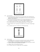
4.3 Hoist Operation 4.3.1 Free Chain Principle Free chaining allows the load chain to be moved freely because the brake is released under no load situations. Pulling the free knob actuates the internal spring to release the mechanical brake allowing the load chain to be pulled in either direction to the desired length. Refer to Figure 4-1. The brake is engaged during lowering or lifting the load. Figure 4-1 Free Chain Mode 4.3.
4.3.3 Lifting and Lowering Operation – Operating the lever with the selector set to the lifting “UP” or the lowering “DN” position, the hoist performs as follows: Set the selector to the direction of load movement desired and ratchet the lever back and forth. Refer to Table 4-1. In lifting mode, the mechanical brake is engaged and supports the load on the pawls when the lever stops.
4.4.8 Load Limit Warning Handle Operation Operate the hoist by holding the middle of the lever grip. The following three (3) signals occur to warn of an excessive load. Refer to Figure 4-2. - The lever grip DEFLECTS. - The lever CLICKS. - The signal window changes from GREEN to RED. Stop lifting and lowering immediately when an overload is detected. Reset the grip into its straight position (back in place) before continuing to operate the hoist.
Figure 4-3 Slip Clutch Identifier Label 4.5.2 If the Slip Clutch is activated, immediately stop the lifting operation and ensure that the lever hoist is in a no load state. Follow the Owner‟s Manual to operate the lever hoist in a normal manner. Slip Clutch Operation Precautions Do not lift more than the rated load. When the Slip Clutch is activated, stop operating the hoist immediately. Failure to follow this instruction may cause injury or damage to the product.
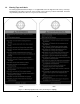
5.0 Inspection 5.1 General 5.1.1 5.2 The inspection procedure herein is based on ANSI/ASME B30.21. The following definitions are from ANSI/ASME B30.21 and pertain to the inspection procedure below. Designated Person – a person selected or assigned as being competent to perform the specific duties to which he/she is assigned.
5.3 Frequent Inspection 5.3.1 Inspections should be made on a FREQUENT basis in accordance with Table 5-1, “Frequent Inspection.” Included in these FREQUENT Inspections are observations made during operation for any defects or damage that might appear between Periodic Inspections. Evaluation and resolution of the results of FREQUENT Inspections shall be made by a designated person such that the hoist is maintained in safe working condition.
5.5 Occasionally Used Hoists 5.5.1 5.6 5.7 Hoists that are used infrequently shall be inspected as follows prior to placing in service: Hoist Idle More Than 1 Month, Less Than 1 Year: Inspect per FREQUENT Inspection criteria in Section 5.3. Hoist Idle More Than 1 Year: Inspect per PERIODIC Inspection criteria in Section 5.4. Inspection Records 5.6.
Table 5-3 Hoist Inspection Methods and Criteria Item Method Criteria Action Lifting System – Components Visual Components should not be deformed, scarred or show significant wear. Refer to Figure 5-4. Replace Lifting System – Selector Pawl Spring Measure The “L” dimension should not be less than the listed in Table 5-7. Replace Lifting System – Brake Spring Measure The “L” dimension should not be less than the listed in Table 5-8.
Table 5-3 Hoist Inspection Methods and Criteria Item Method Criteria Action Top Pin – Deformation Visual, Measure The pin should be free of scars or significant deformation. The "d" dimension should not be less than discard value listed in Table 5-11. Replace Yoke – Top Pin Hole Deformation Visual, Measure The "d" dimension of the top pin hole should not be greater than the discard value listed in Table 5-12.
Figure 5-1 Body Components Figure 5-2 Other Components 26
Figure 5-3 Braking System Components Table 5-4 Friction Plate Wear Dimensions Thickness inch (mm) Product Code All Standard Discard 0.14 (3.5) 0.12 (3.0) Table 5-5 Brake Bushing Wear Dimensions A Dimension inch (mm) Product Code All Standard Discard 0.16 (4.0) 0.12 (3.
Table 5-6 Brake Ratchet Disc Wear Dimensions D Dimension inch (mm) Product Code Standard Discard LB008, LB010, LB015, LB020, LB028 2.52 (64) 2.40 (61) LB030, LB060, LB090 2.91 (74) 2.
Table 5-7 Selector Pawl Spring Length Dimension L Dimension inch (mm) Product Code Standard LB008, LB010, LB015, LB020, LB028 1.46 (37) LB030, LB060, LB090 1.65 (42) Table 5-8 Lifting Brake Spring Dimensions Product Code L Dimension Inches (mm) Discard Non Slip Clutch With Slip Clutch LB008, LB010, LB015,LB020, LB028 LB030, LB060, LB090 A Dimension (degrees) Standard Discard 30 45 25 40 1.18 (30) LB008, LB010, LB015,LB020, LB028 1.18 (30) 30 45 LB030, LB060, LB090 0.
Table 5-9 Free Chain Spring Dimensions Product Code Non Slip Clutch With Slip Clutch L Dimension Inches (mm) Standard Discard LB008, LB010 LB015, LB020, LB028 2.60 (66) 2.32 (59) LB030, LB060, LB090 2.80 (71) 2.52 (64) 2.64 (67) 2.95 (75) LB008, LB010 LB015LB020, LB028 LB030, LB060, LB090 A Dimension (degrees) Standard Discard 180 165 2.36 (60) 145 160 2.
Hook Swivel Twisted Hook Figure 5-5 Top and Bottom Hooks Table 5-11 Body Top Pin Wear Dimensions d Dimension inch (mm) Product Code Standard Discard LB008, LB010 LB015 0.47 (12) 0.45 (11.4) LB020, LB028 0.55 (14) 0.52 (13.3) LB030, LB060, LB090 0.63 (16) 0.60 (15.2) Table 5-12 Chain Pin Hole and Top Pin Hole Wear Dimensions Hole Diameter (d) Product Code Chain Pin Hole inch (mm) Top Pin inch (mm) Standard Discard Standard Discard LB008, LB010 0.28 (7.1) 0.30 (7.6) 0.48 (12.2) 0.
Table 5-13 Chain Wear Dimensions “P” Dimension inch (mm) Product Code “d” Dimension inch (mm) Standard Discard Standard Discard LB008, LB010 3.11 (79.0) 3.20 (81.3) 0.22 (5.6) 0.20 (5.1) LB015 3.94 (100.0) 4.05 (102.9) 0.28 (7.1) 0.25 (6.4) LB020, LB028 4.88 (124.0) 5.02 (127.6) 0.35 (8.8) 0.31 (7.9) LB030, LB060, LB090 5.55 (141.0) 5.71 (145.1) 0.39 (10.0) 0.35 (9.0) Table 5-14 Chain Pin Wear Dimensions “d” Dimension inch (mm) Product Code Standard Discard LB008, LB010 0.
6.0 Maintenance and Handling 6.1 Lubrication 6.1.1 Load Chain Model L4 and Model L5 chain is not interchangeable. For longer life, the load chain should be lubricated. The load chain lubrication should be accomplished after cleaning the load chain with an acid free cleaning solution. Apply Harrington lubricating grease (Part No. ER1BS1951) or an equivalent to industrial general lithium grease, NLGI No.
6.2 Disassembly, Assembly and Adjustment 6.2.1 1) Perform proper disassembly or assembly in accordance with this manual. 2) The hoist utilizes dry friction plates; they are not to be lubricated. 3) Do not extend the load chain. 4) Remove old grease on the disassembled parts. 5) Replace components with Harrington Hoist approved parts. 6) To reassemble, apply new grease, and use a new split pin and snap ring. Note: The following symbols in this manual indicate the recommended lubricants. G1: NLGI No.
6.3.2 Lever 1) Remove (31) Acorn nuts and (32) Spring Lock Washers, which attaches (29) Brake Cover assembly to (10) Frame A assembly. 2) While holding (37) Lever assembly horizontally by hand, turn (33) Female Thread counterclockwise and remove the lever assembly (29) Brake Cover assembly from the hoist. 3) Remove (42) Hex Cap Screw and (30) Flange Nut, and separate (37) Lever assembly and (29) Brake cover assembly. 4) Remove (33) Female Thread from (29) Brake cover assembly.
6.4.2 Lever Refer to Figure 6-1, proceed as follows: 1) Set the Selector Lever on the (37) lever assembly to the „N‟ position. 2) With the Selector Lever pulled in the „a‟ direction, as shown in the left picture, insert the hex part of the Selector Lever into (34) Select pawl. 3) Apply (G1) grease lightly to the pawl of (34) Select Pawl and to the top of (35) Spring Shaft as shown in Figure 6-1. 4) Insert (35) Spring Shaft into (36) Select-Pawl spring and attach them into the Spring Holder.
6.4.3 Lever Grip 1) Read ALL instructions below BEFORE applying glue. 2) Remove dirt, water, oil and rust from the area of the Lever where the glue will be applied for the new grip. Note: Glue is included with the replacement Lever Grip. 3) Make a quick and even application of the glue on the four sides of the Lever as shown in Figure 63. (38) Grip must be installed within 10 seconds after applying the glue to the Lever.
6.4.4 Load Sheave and Chain Assembly 1) For LB008 to LB030 hoists attach (4) Bottom Hook set to (52) Load chain with (8) Slotted Nut and (7) Split Pin. 2) For LB060 and LB090 hoists apply (G1) grease the bearing surface of the (17) Shaft Assembly and (16) (17) Idle Sheave. Install the shaft and sheave into the (13) Bottom or (4) Top Yoke assembly and secure the yokes with (14) bolts and (15) Lever Nuts.
7) Apply (G3) grease to the bearing part of (12) Frame B. Refer to Figure 6-7. 8) Install (12) Frame B onto (10) Frame A Stay Bolts. Make sure to align the top flat parts of the both frames. Figure 6-7 Frame B 6.4.5 Top Hook Install the (1) Top hook set between (10) Frame A assembly and (12) Frame B then Insert (3) Top pin from the side of (12) Frame B to fasten (1) Top hook set. Refer to Figure 6-8.
6.4.6 Gears 1) For LB020 to LB090 hoists, attach (18) Load Gear to the serrated part of (19) Load Sheave. If necessary use a plastic or rubber hammer to make the load gear is fully seated on the Load Sheave. 2) Insert (16) Pinion into (19) Load Sheave and install (17) Gear #2 as shown in Figure 6-9. Gear #2 must be timed with the “0” marks as shown for the gears to rotate freely. Figure 6-9 Gears 3) Apply (G1) grease to (16) Pinion, (17) Gear #2 and (18) Load Gear.
6.4.7 Brake 1) Lightly apply (G2) grease to the Pawl Shaft and (22) Pawl. Refer to Figure 6-10. 2) Use a minimal amount of grease on (22) Pawl to avoid getting grease on the friction surfaces of the brake. 3) Fasten two sets of (23) Pawl Spring and (22) Pawl with (24) Snap Ring. Figure 6-10 Pawl Shaft and Pawl 4) While holding two (22) pawls outward, install (25) Friction Disc, (26) Friction Plate, (28) Bushing, (27) Ratchet Disc and (26) Friction Plate properly in this order.
6.4.8 Hoist Lever and Body 1) Attach the Lever assembled in Section 6.4.2 to the previously assembled Brake. Fit (29) Brake Cover assembly and (10) Frame A assembly by screwing (33) Female Thread of the Lever assembly clockwise to the thread of (16) Pinion until it makes a clicking sound. Make sure the flat part of the Brake Cover aligns with the flat on Frame A. 2) Fasten (29) Brake Cover assembly firmly to the Stay Bolts with (14) Acorn Nuts and (15) Spring Lock Washer.
6.4.9 Free Chain Knob 1) Set (43) Brake Spring (silver color) into the slot of the back of (45) Free Chain Knob assembly. Refer to Figure 6-13. As indicated in Figure 6-13, set the end of the spring next to the rib of the knob. Figure 6-13 Cam Guide and Brake Spring 2) Fit the opposite end of (43) Brake Spring next to the boss of the Female Thread. Refer to Figure 6-14.
Figure 6-15 Brake Spring and Female Thread Assembly 5) Hook the outward-projecting end of (47) Free Chain Spring onto the slot at the back of (48) Spring Holder, and hook the other end (inward-projecting) of the Spring onto the slot of (45) Free Chain Knob assembly. Refer to Figure 6-16. Figure 6-16 Free Chain Knob Assembly 6) Turn (48) Spring Holder 120° counterclockwise while lightly pressing it toward the (45) Free Chain Knob assembly.
Figure 6-17 Free Chain Knob and Spring Holder 6.4.10 Preoperational Checks 1) Make sure all nuts, bolts and split pins are sufficiently fastened. 2) Make sure all components have been installed correctly. 3) After assembly, perform the following preoperational checks before operating hoist. 4) Make sure that the hoist operates properly under no load condition before lifting a load. 5) Perform a load test at 125% of rated load in accordance with ASME B30.21.
7.0 Troubleshooting Read and comply with instructions in this manual and use the hoist properly. Checking the sounds from the hoist in operation is a critical inspection. Note hoist sounds during operation. If a defect is found in the hoist, stop using it immediately and check the cause of the defect. Only Trained and competent personnel should inspect and repair the hoist.
Table 7-1 Troubleshooting Guide Symptom Cause Remedy Reassemble gears properly and ensure smooth operation before reuse. Hoist will not lift – Lever will not operate Ensure the „0‟ marks of gear #2 are aligned properly, as shown. Gear #2 improperly timed Gear #2 Pinion '0' Mark Hoist with Slip Clutch Hoist will not lift – Slip Clutch activated. Reduce load to less than rated capacity. Lever will operate but load will not move.
Table 7-1 Troubleshooting Guide Symptom Cause Remedy Reset the capsized hook. Hoist will not lift all the way (multiple fall hoists) Capsized hook Twisted Chain Capsized Hook and Chain Double Fall Models Improper braking may cause improper load lowering. The hoist utilizes dry friction discs, do not apply oil to friction surfaces.
Table 7-1 Troubleshooting Guide Symptom Cause Remedy Mis-assembly of friction plates, i.e. friction plates missing or at one side as shown. Cracked friction plate caused by overload Reassemble properly as shown and ensure hoist functions properly before reuse. Replace the friction plate and use the hoist properly within rated capacity. Friction plate wear caused by very frequent and long term use. Perform hoist maintenance.
Table 7-1 Troubleshooting Guide Symptom Cause Remedy Reassemble properly.
8.0 Warranty All products sold by Harrington Hoists, Inc.
This Page Intentionally Left Blank 52
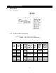
9.0 Parts List When ordering Parts, please provide the Hoist code number, lot number and serial number located on the Hoist nameplate (see Figure 9-1 below). Reminder: Per Sections 1.1 and 3.4.4 to aid in ordering parts and product support, record the hoist Code, Lot and Serial Number in the space provided on the cover of this manual. Figure 9-1 LB Nameplate Figure 9-2 LB with Slip Clutch Nameplate The parts list is arranged into the following sections: Section Page 9.1 3/4 to 3 Ton Parts………………….
9.1 3/4 to 3 Ton Parts MODEL L4 AND MODEL L5 CHAIN IS NOT INTERCHANGEABLE.
9.1 3/4 to 3 Ton Parts Fig. No. 1 2 3 4 5 7 8 9 10 11 12 13 14 15 16 17 18 19 20 21 22 23 24 25 26 27 28 29 30 31 32 33 34 35 36 37 38 39 40 42 43 44 45 46 47 48 49 50 52 53 54 Name Parts Per Hoist Top Hook Comp. Set Latch Assembly Top Pin Bottom Hook Comp.
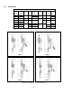
9.2 Additional 6 and 9 Ton Parts MODEL L4 AND MODEL L5 CHAIN IS NOT INTERCHANGEABLE. 6 Ton 9 Ton Figure 9-3 6 and 9 Ton Parts Figure No. 1 2 3 4 5 6 7 8 9 Name Top Hook Complete Set Hook Assembly Latch Assembly Top Yoke Assembly Socket Bolt Lever Nut Idle Sheave Shaft Assembly Shaft Stopper Pin Parts Per Hoist 6 Ton 1 1 1 L5BU0601001 L5BA0631071 9 Ton Figure No.
9.3 Optional Parts Figure 9-4 Load Limit Warning Handle Load Limit Warning Handle Fig. No.
9.3 Optional Parts Figure 9-5 Bullard®, Shur-Loc® and Inspection Hooks ® Bullard Hooks Fig. No.
9.3 Optional Parts ® Shur-Loc Hooks Fig. No.
9.3 Optional Parts Figure 9-6 Shipyard Hooks Shipyard Hooks Fig. No.
9.3 Optional Parts Figure 9-7 Top Hook Extender Top Hook Extender Fig. No.
9.3 Optional Parts Figure 9-8 Slip Clutch Slip Clutch Fig. No.
NOTES 63
www.harringtonhoists.com Harrington Hoists, Inc. 401 West End Avenue Manheim, PA 17545-1703 Phone: 717-665-2000 Toll Free: 800-233-3010 Fax: 717-665-2861 Harrington Hoists – Western Division 2341 Pomona Rd.