EFFECTIVE: May 2, 2012 HPC500 Series Top Running and Underhung End Trucks ½ Ton, 1 Ton, and 2 Ton Capacity Code and Serial No. This equipment should not be installed, operated or maintained by any person who has not read and understood all the contents of this manual. Failure to read and comply with the contents of this manual can result in serious bodily injury or death, and/or property damage.
Table of Contents Section Page Number 1.0 Important Information and Warnings………………………………………………….………………….4 1.1 Terms and Summary 1.2 Warning Tags and Labels 2.0 Technical Information………………………………………………………………………..…..…….…..7 2.1 Specifications 2.2 Part Names 3.0 Pre-operational Procedure…………………………………………………..…….................................11 3.1 Runway 3.2 Bridge Beam 3.3 End Trucks 3.4 Pre-operational Checks and Trial Operation 4.0 Operation………………………………………………………………………………………………….19 4.
6.0 Lubrication……………………………………………………………………….……..…..…...……25 7.0 6.1 HPC500 End Trucks 6.2 Other Equipment Maintenance & Handling……………………………………………………………………………26 7.1 General 7.2 Storage 7.3 Outdoor Installations 8.0 Troubleshooting ……………………………………………………………………..…….….…….27 9.0 Warranty………………………………………………………………………………...……...……28 10.0 Parts List……………………………………………………………………………...……….……..
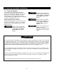
1.0 Important Information and Warnings 1.1 Terms and Summary This manual provides important information for personnel involved with the installation, operation, and maintenance of this product. Although you may be familiar with this or similar equipment, it is strongly recommended that you read this manual before installing, operating, or maintaining the product.
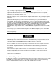
Equipment described herein is not designed for and MUST NOT be used for lifting, supporting, or transporting people, or for lifting or supporting loads over people. Equipment described herein should not be used in conjunction with other equipment unless necessary and/or required safety devices applicable to the system, crane, or application are installed by the system designer, system manufacturer, crane manufacturer, installer, or user.
1.2 Conformance Statement In order to meet requirements of the Crane Manufacturers Association of America (CMAA), the National Electric Code (NEC) and the American National Standards Institute (ANSI/ASME) Harrington components include: Thermal motor protection for all motors. Rubber bumpers. Hoists load tested to 125% of rated capacity. Drop stops for all end trucks. Rail sweeps for all end trucks. Recommended bridge beams comply with CMAA.
2.0 Technical Information 2.1 Specifications 2.1.1 Product Codes (a) HPC505 up to ½ Ton capacity (b) HPC510 up to 1 Ton capacity (c) HPC520 up to 2 Ton capacity 2.1.2 Description The HPC500 Series End Truck Kit includes two 4-wheeled end trucks with rubber bumpers, bridge beam end stops, bridge beam fastener hardware, bridge beam assembly drawing, and this Owner’s Manual & Parts List. The HPC500 End Truck is designed to meet CMAA requirements for Class B Medium Duty Cranes.
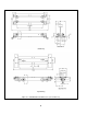
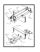
Underhung Top Running Figure 2-1 HPC500 End Truck Dimensions (refer to Table 2-1) 8
2.
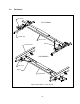
UNDERHUNG SWEEP FRAME WHEEL END BRACKET B END BRACKET A BUMPER TOP RUNNING END BRACKET B WHEEL END BRACKET A FRAME BUMPER SWEEP Figure 2-3 Part Names – End Truck 10
3.0 Pre - operational Procedures 3.1 Runway 3.1.1 Crane systems must be intalled on runways that are properly designed, fabricated, installed, and supported. The runway must meet the requirements of CMAA Specification 74. 3.1.2 3.1.3 All operations associated with the assembly and installation of the end trucks and/or the crane system should be performed under the supervision of a Qualified Person (see Section 5 for the definition of Qualified Person). 3.1.
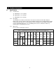
Table 3-1 Bridge Beams for a MANUAL or ELECTRIC HOIST on an HPC500 Crane Important information about this table: Includes 15% Allowance for Electric Hoist Load Factor. Based on Harrington’s manual chain hoist product. For spans greater than 10 ft., braces between end truck & bridge beam should be used. Maximum Allowable Span (ft) Cap. (Tons) 10 15 20 24 ½ S8 X 18.4 S8 X 18.4 S8 X 18.4 S10 X 25.4 1 S8 X 18.4 S8 X 18.4 S10 X 25.4 S10 X 25.4 2 S10 X 25.4 S10 X 25.4 S12 X 31.8 3.2.
SPAN 7 7 2 2 BEAM FLANGE HOLES (from Fig. 3-1) Figure 3-3 Bridge Beam Web Holes – TOP RUNNING 3.2.5 End Stop Installation – This step covers the installation of the end stops onto the bridge beam. Locate the holes that were installed in the web of the bridge beam (step 3.2.4 above). These are the holes for attaching the end stops to the bridge beam. Attach the four (4) end stops to the bridge beam in accordance with Figure 3-4. Fully tighten the fasteners by applying 75 ft-lb of torque.
3.3 End Trucks 3.3.1 3.3.2 3.3.3 Read through all steps completely before proceeding with installation. All operations associated with the assembly and installation of the end trucks and/or the crane system should be performed under the supervision of a Qualified Person (see Section 5 for the definition of Qualified Person).
FLAT WASHER (HPC 505 ONLY) FLAT WASHER HEX NUT *NOTE: DROP STOP NOT SHOWN FOR CLARITY. WHEEL ASSEMBLY FRAME* LOCK WASHER Figure 3-6 Wheel Assembly Installation Underhung Top Running Figure 3-7 Wheel Mounting Locations 3.3.5 Verify “H” Dimension – The “H” dimension is the End Truck Frame Spacing (see Table 2-1 and Figure 2-1). By verifying the “H” dimension you verify that the end bracket holes are correct for proper fit of the end truck onto the runway.
RUNWAY BEAM FRAME 3 APPROX. 16 END BRACKET 3 APPROX. 16 H UNDERHUNG Figure 3-8 Verify “H” Dimension RUNWAY BEAM HEX-HEAD CAP SCREW HEX NUT HEX NUT FLAT WASHER FLAT WASHER FLAT WASHER HEX NUT HEX NUT FLAT WASHER UNDERHUNG HEX-HEAD CAP SCREW RUNWAY RAIL TO P R U N N IN G Figure 3-9 End Truck Assembly & Installation 3.3.6 End Truck Assembly & Installation – Here the assembly of the end trucks is completed and they are installed onto the runway.
3.3.7 Ensure that the “H” dimension is correct as determined in step 3.3.5 above, and tighten the fasteners by applying 75 ft-lb of torque. Top Running – apply the following steps for each end truck: - Ensure that the “H” dimension is correct as determined in step 3.3.5 above, and tighten the fasteners by applying 75 ft-lb of torque. - Place the end truck onto the runway rail (or square bar) in accordance with the Top Running part of Figure 3-8.
END TRUCK 90° BRIDGE BEAM 90° Figure 3-11 Crane Squareness 3.4 Pre-operational Checks and Trial Operation 3.4.1 Record the end trucks’ Code and Serial No. from the nameplate (see Figure 10-1) in the space provided on the cover of this manual. 3.4.2 Ensure that the end trucks are properly installed on the runway beams/rails. 3.4.3 If the end trucks are used as part of an overhead travelling bridge crane, then make sure that the bridge beam is properly designed, fabricated, and installed. 3.4.
4.0 Operation 4.1 Introduction Specific operation instructions are not provided herein because the HPC500 series end trucks are used in systems not covered by this Owner’s Manual. Nevertheless, operation of systems using the HPC500 end trucks is an EXTREMELY IMPORTANT issue – following is important information about operation. 4.2 Important Information About Operation Do not walk under a suspended load. Do not use HPC500 end trucks in systems that lift, support, or transport people.
5.0 Inspection 5.1 General 5.1.1 The inspection instructions herein are limited to the HPC500 Series End Trucks and Harringtondesigned HPC500 Cranes, and are based on the use of these products for overhead cranes and monorails as defined by the following standards. ANSI/ASME B30.11 Monorails and Underhung Cranes ANSI/ASME B30.16 Overhead Hoists (Underhung) ANSI/ASME B30.
5.3 Severe service - quarterly Special or Infrequent Service – as recommended by a Qualified Person Frequent Inspection 5.3.1 Use the following as guidance for inspections to be made on a FREQUENT basis. 5.4 Inspect all functional operating mechanisms for: - Proper Operation - Proper Adjustment - Unusual Sounds If a hoist/trolley is included in the system, perform inspection in accordance with the manufacturer’s recommendations for FREQUENT inspection.
5.5 Occasionally Used End Trucks and Cranes 5.5.1 5.6 End Trucks and cranes that are used infrequently shall be inspected as follows prior to placing in service: Idle More Than 1 Month, Less Than 1 Year: Inspect per FREQUENT Inspection criteria of Section 5.3 above. Idle More Than 1 Year: Inspect per PERIODIC Inspection criteria of Section 5.4 above. Inspection Records Dated inspection reports and records should be maintained for PERIODIC inspections.
Table 5-2 Inspections Methods and Criteria Component Item Method End Truck Corrective Action Fasteners Check tightness Measure torque Fasteners must be sufficiently tight. Refer to torque values listed in Section 3. Tighten Wheel Running Surfaces Visual The surfaces on which the end truck wheels run must be free of oil, grease or paint. Clean/remove contaminants Wheel Running Surfaces Visual The surfaces on which the end truck wheels run must not be worn excessively. Replace.
Table 5-3 Wheel Tread Diameter End Truck Code Standard Value (in) Min. Value for Replacement (in) HPC505 3.12 2.97 HPC510 4.00 3.81 HPC520 4.88 4.
6.0 Lubrication 6.1 HPC500 End Trucks 6.1.1 6.2 There are no lubrication requirements for the HPC500 Series End Trucks for the following reasons. The wheel bearings are sealed and permanently lubricated. There are no other components that are lubricated or which require lubrication. Other Equipment 6.2.
7.0 Maintenance and Handling 7.1 General 7.1.1 The HPC500 Series End Truck is designed to be MAINTENANCE-FREE. If a hoist/trolley (or some other type of equipment) is used in the system, then perform maintenance and handling of the hoist/trolley (or other equipment) in accordance with the manufacturer’s requirements and recommendations. 7.2 7.3 Storage 7.2.1 Whenever the end trucks are to be placed into storage, place extra grease onto all exposed unpainted parts such as the wheels and fasteners.
8.0 Troubleshooting Use Table 8-1, “Troubleshooting Guide” below to troubleshoot any problems you may encounter with the HPC500 Series End Truck or Crane. Table 8-1 Troubleshooting Guide Trouble Cause Remedy Make sure the span of the runway system is within the allowable tolerance of CMAA Spec 74.
9.0 Warranty Warranty explanation and terms. All products sold by Harrington Hoists, Inc.
10.0 Parts List When ordering Parts, please provide the Code number located on the end truck nameplate (see Figure 10-1 below). Reminder: Per Sections 1.1 and 3.4.1, to aid in ordering Parts and Product Support, record the end trucks’ Code and Serial No. in the space provided on the cover of this manual.
Table 10-1 Parts List for HPC500 Series End Trucks Figure Number Qty/Pr HPC505 HPC510 HPC520 PART NAME 1 4 52391 52390 62674 Frame Assembly 2 2 3 2 6 2 7 8 8 8 9 4 10 16 62675 End Bracket A – Standard Flange Range 62678 End Bracket A – Extended Flange Range 62676 End Bracket B – Standard Flange Range End Bracket B – Extended Flange Range 62679 80065 80066 80067 9003903 9003905 Nut 9003908 Nut 9004603 Bumper 9005209 8 Flat Washer 9005212 9005313 Name Plate 11 8
NOTES 31
www.harringtonhoists.com Harrington Hoists, Inc. 401 West End Avenue Manheim, PA 17545 Phone: 717-665-2000 Toll Free: 800-233-3010 Fax: 717-665-2861 Harrington Hoists - Western Division 2341 Pomona Rd.