
User Manual


3.7 Electrical/A ir Connections
3.7.1 This instruction applies to a Harrington Powered hoist attached to a Push or Geared Trolley. Refer to
the appropriate hoist’s owner’s manual for the Electrical or Air connections.
3.7.2
B efore proceeding, ensure that the electrical supply for the hoist has been de-
energized (disconnected). Lock out and tag out in accordance with ANSI Z244.1 “Personnel Protection
-Lockout/Tagout of Energy Sources”.
3.7.3
B efore proceeding, ensure that the air supply for the hoist has been de-energized
(disconnected). Lock out and tag out in accordacne with ANSI Z244.1 “Personnel Protection-Lockout of
Energy Sources”.
Power Supply Cable /Air Supply – Installation
Cable must be installed along the beam that the trolley runs on. For curved beams a special
cable suspension system will be needed, and this instruction does not apply. For straight
beams install the power supply cable as follows:
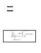
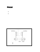
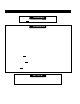
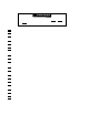
Install a guide wire system parallel to the beam. (See Figure 3-39)
The guide wire should be positioned slightly outside the hoist’s Cable Support.
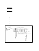
Use the Cable Trolleys supplied with the hoist to suspend the Power Supply Cable/Air
Supply Hose from the guide wire. Space the Cable Trolleys every 5 feet.
Make sure the Guide Wire is properly tensioned and the Power Supply Cable/Air Supply
Hose is not twisted or kinked.
Festoon Cable should not make any contact with any component of hoist or trolley.
Figure 3-39 Power Supply Cable/A ir Supply H ose ins tallation and Gui de Wire l ocation.
47