
User Manual
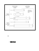


6) For the (N)ER/(N)E R2 hoi sts – Insert the Trolley Fixing Shaft through Side Plate G, Suspension plates and Side
Plate S. Refer to Figure 3-30. Secure it to side Plate G with two split pins. Securely bend both branches of the
Split Pin after insertion.
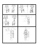
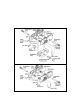
Figure 3-29 Assembling the Trolley - 8 Through 10 Ton Capaci ty, CB or TCR
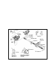
Note: Trolley F ix ing Shaft is sh ow n in front of S uspen sion S haf t for c larit y. A ctual locat ion i s behi nd t he
Suspensio n S haft.
Figure 3-30 As sembling the Troll ey - 8 Through 1 0 Ton Capa city, (N )ER/(N)E R2
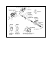
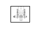
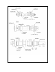
Refer to Figure 3-31 for 15-20 Ton coupled with Manual CB hoist
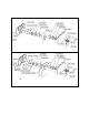
Refer to Figure 3-32 for 15-20 Ton coupled with (N)ER/(N)ER2 hoist
1) Remove the Shaft Stopper Pin, Side Plate S, and Spacers from the Suspension Shaft. For beam flanges that are
wider than the standard range, different suspension shaft and/or spacer arrangements are provided. Refer to
Table 3-1.
34