EFFECTIVE: February 14, 2014 MANUAL TROLLEY TF2/TS2 SERIES 1/2 Ton through 20 Ton Capacity Code, Lot and Serial Number This equipment should not be installed, operated or maintained by any person who has not read and understood all the contents of this manual. Failure to read and comply with the contents of this manual can result in serious bodily injury or death, and/or property damage.
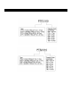
Table of Contents Section 1.0 2.0 3.0 4.0 5.0 Page Number Important Information and Warnings………………………………………………………………………. 4 1.1 Terms and Summary 1.2 Warning Tags and Labels Technical Information ………………………………………………………………………………………. 8 2.1 Specifications 2.2 Dimensions 2.3 Optional Equipment Pre-operational Procedures………………………………………………………………………………...18 3.1 Manual Hoist Adjustment for Trolley 3.2 Electric Hoist Adjustment for Trolley 3.3 Air Power Hoist Adjustment for Trolley 3.
Section 6.0 Page Number 5.4 Periodic Inspection 5.5 Occasionally Used Trolleys 5.6 Inspection Records 5.7 Inspection Methods and Criteria Maintenance & Handling…………………………………………………………………………………..58 6.1 Lubrication 6.2 Storage 6.3 Outdoor Installation 7.0 Warranty…………………………………………………………………………………………………….59 8.0 Parts List…………………………………………………………………………………………………….61 8.1 TF2 Push Trolley Parts – 1/8 to 5 Ton 8.2 TF2 Geared Trolley Parts – 1/8 to 5 Ton 8.
1.0 Important Information and Warnings 1.1 Terms and Summary This manual provides important information for personnel involved with the installation, operation and maintenance of this product. Although you may be familiar with this or similar equipment, it is strongly recommended that you read this manual before installing, operating or maintaining the product. Danger, Warning, Caution and Notice - Throughout this manual there are steps and procedures that can present hazardous situations.
Equipment described herein is not designed for and MUST NOT be used for lifting, supporting, or transporting people, or for lifting or supporting loads over people. Equipment described herein should not be used in conjunction with other equipment unless necessary and/or required safety devices applicable to the system, crane, or application are installed by the system designer, system manufacturer, crane manufacturer, installer, or user.
HAZARDOUS VOLTAGES ARE PRESENT IN THE HOIST CONTROL BOX, OTHER ELECTRICAL COMPONENTS, AND CONNECTIONS BETWEEN THESE COMPONENTS. Before performing ANY mechanical or electrical maintenance on the equipment, de-energize (disconnect) the main switch supplying power to the equipment; and lock and tag the main switch in the de-energized position. Refer to ANSI Z244.1, “Personnel Protection – Lockout/Tagout of Energy Sources”. Only trained and competent personnel should inspect and repair this equipment.
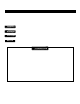
1.2 Warning Tag and Labels The warning tag illustrated below in Figure 1-1 is supplied with each trolley shipped from the factory. If the tag is not attached to the pendant cord for your hoist/trolley, order a tag from your dealer and install it. Read and obey all warnings attached to this trolley. Tag is not shown actual size.
2.0 Technical Information 2.1 Specifications 2.1.1 Product Code for TF2 Trolley: 2.1.2 Product Code for TS2 Trolley: 2.1.
2.1.4 PTF2 Specifications Table 2-1 PTF2 Trolley Specifications Cap. (Tons) 2.1.5 Product Code Min. Radius for Curve (in) Standard Option Flange Width Adjustability B (in) Approx. Net Weight (lbs) 1/2 PTF2005 13.8 2.28 to 4.00 4.01 to 8.00 or 8.01 to 12.00 9 1 PTF2010 17.7 2.28 to 5.00 5.01 to 8.00 or 8.01 to 12.00 15 1 1/2-2 PTF2020 21.7 3.23 to 6.02 6.03 to 12.00 29 2 1/2-3 PTF2030 25.6 46 5 PTF2050 78.7 4.92 to 7.02 7.03 to 12.00 95 8 PTF080 118.1 5.50 to 8.66 8.
2.1.6 GTF2 Specifications Table 2-3 GTF2 Trolley Specifications Cap. (Tons) Product Code Min. Radius for Curve (in) Standard Option 2.28 to 5.00 5.01 to 8.00 or 8.01 to 12.00 3.23 to 6.02 6.03 to 12.00 1 GTF2010 17.7 1 1/2-2 GTF2020 21.7 2 1/2-3 GTF2030 25.6 5 GTF2050 78.7 8 GTF080 10 GTF100 15 GTF150 20 GTF200 Flange Width Adjustability B (in) ER2 CB 24 38 55 4.92 to 7.02 7.03 to 12.00 118.1 5.50 to 8.66 2.1.7 Approx. Net Weight (lbs) 104 248 218 490 534 8.
2.2 Dimensions 2.2.1 PTF2 Dimensions Table 2-5 PTF2 Trolley Dimensions PTF2005 to PTF2030 Cap. (Tons) Product Code a max (in) 1/2 PTF2005 6.8 PTF2050 to PTF100 a' (in) b (in) e (ft) h (in) i (in) j (in) k (in) m (in) n (in) r (in) s (in) t (in) v (in) 8.0 7.2 1.8 3.2 2.36 0.80 3.0 2.7 3.3 1.5 B-1.8 0.87 3.7 1.1 1 PTF2010 8.5 9.8 9.3 2.2 4.2 2.80 1 1/2-2 PTF2020 10.4 11.8 11.0 2.7 5.0 3.35 3.7 3.1 4.4 2.0 B-1.9 0.98 4.2 4.4 3.8 5.2 2.4 B-2.3 1.
2.2.2 PTS2 Dimensions Table 2-6 PTS2 Trolley Dimensions PTS2005 to PTS2030 Cap. (Tons) Product Code a max (in) a' (in) b (in) PTS2050 to PTS100 e (ft) h (in) i (in) j (in) k (in) m (in) n (in) r (in) s (in) t (in) v (in) 1/2 PTS2005 6.8 8.0 7.2 1.8 3.2 2.36 0.7 3.0 2.7 3.3 1.5 B-1.8 0.87 3.7 1 PTS2010 8.5 9.8 9.3 2.2 4.2 2.80 1.1 3.7 3.1 4.4 2.0 B-1.9 0.98 4.2 1 1/2-2 PTS2020 10.4 11.8 11.0 2.7 5.0 3.35 1.3 4.4 3.8 5.2 2.4 B-2.3 1.26 5.
2.2.3 GTF2 Dimensions Table 2-7 GTF2 Trolley Dimensions GTF2010 to GTF2030 GTF2050 to GTF2100 GTF2150 to GTF2200 Cap. (Tons) Product Code a max* (in) ER2 CB a' max (in) ER2 b (in) CB m (in) e (in) ER2 1/2-1 GTF2010 10.8 13.6 9.3 6.0 1 1/2-2 GTF2020 13.7 15.2 11.0 6.1 2 1/2-3 GTF2030 14.1 15.7 12.8 6.2 5 GTF2050 14.8 15.8 13.7 6.1 8 GTF080 10 GTF100 15 GTF150 20 GTF200 f (ft.) h (in) i (in) j (in) k (in) k' (in) CB 8 7.
2.2.4 GTS2 Dimensions Table 2-8 GTS2 Trolley Dimensions GTS2010 to GTS2030 GTS2050 to GTS2100 GTS2150 to GTS2200 Cap. (Tons) Product Code a max* (in) ER2 CB a’ max (in) ER2 b (in) CB e (in) f (ft.) h (in) i (in) ER2 CB 1/2-1 GTS2010 10.8 13.6 9.3 6.0 1 1/2-2 GTS2020 13.7 15.2 11.0 6.1 2 1/2-3 GTS2030 14.1 15.7 12.8 6.2 5 GTS2050 14.8 15.8 15.8 6.1 8 GTS080 10 GTS100 15 GTS150 20 GTS200 m (in) j k k' (in) (in) (in) 41.
2.3 Optional Equipment 2.3.1 Suspender C Table 2-9 Suspender C Dimensions 2.3.2 Capacities (Tons) a (in) b (in) c (in) d (in) e (in) f (in) 1/2 1.0 1.3 0.6 0.87 2.1 2.6 1 1.1 1.5 0.7 0.99 2.2 2.7 2 1.3 1.6 0.9 1.27 2.7 3.2 2 1/2 1.4 1.7 1.0 1.43 3.0 3.6 3 1.6 1.9 1.2 1.43 4.0 4.5 5 2.4 2.8 1.4 2.13 5.5 6.1 Suspender H Table 2-10 Suspender H Dimensions Capacities (Tons) a (in) b (in) c (in) d (in) e (in) 1/4-1/2 1.0 1.3 0.4 0.91 2.3 1 1.
2.3.3 Suspender E & G Table 2-11 Suspender E & G Dimensions Suspender Capacities (Ton) d1 D d2 B P L T W 1/8 to ½ 0.874 1.46 0.480 1.30 2.36 3.60 1.06 0.94 1 0.992 1.65 0.480 1.30 2.72 4.06 1.06 0.94 1 1/2 to 2 1.268 2.13 0.795 1.73 2.99 4.84 1.54 1.42 2 1/2 to 3 1.425 2.48 0.795 1.73 3.35 5.47 1.54 1.77 5 2.13 3.23 1.11 1.93 3.35 6.22 2.32 2.
2.3.4 TCR Suspender (used for Air Hoist) Table 2-12 TCR Suspender Dimensions TCR250, TCR500, TCR1000, TCR3000 TCR1000-2, TCR2000-2 TCR6000-2 TCR10000-2 Model Hoist Suspender P/N Cap (Ton) a (in) b (in) c (in) d (in) e (in) f (in) TCR250 TCR500 6040204 ¼ TO ½ 2.00 5.33 3.78 .875 1.10 R 1.00 0.512 TCR1000 6040201 1 2.00 5.33 3.78 1.230 1.10 R 1.00 0.512 TCR1000-2 60403 1 3.00 5.38 3.78 1.230 1.10 -- 0.512 TCR2000-2 6040403 2 3.25 5.56 3.54 1.703 1.10 -- 0.
3.0 Pre-operational Procedures 3.1 Manual Hoist Adjustment for Trolley 3.1.1 For ½ - 5 Ton capacities, Harrington’s Model CB Series chain hoist can be Hook mounted to the TF2/TS2 Trolley using suspender “C” as shown in Figure 3-1 or Lug mounted to suspender “C” as shown in Figure 3-2 Figure 3-1 ½-5 Ton CB Hook Mount 3.1.2 Figure 3-2 ½-5 Ton CB Lug Mount Direct coupling lug mounted method for CB Series. 1) For ½ to 2 ½ Ton capacity Refer to Figure 3-3.
9) Straighten and remove the spit pin in the top shaft pin and remove the top shaft pin, remove the top hook. 10) Mount suspender “C” (large) in place of the top hook, insert the top shaft pin and re-insert the split pin. 11) Replace the wheel cover. 12) Attach Hoist to Trolley. Figure 3-4 Installing suspender “C” 3 to 5 Ton capacity 3.1.3 For 8 and 10 Ton capacities, Harrington’s Model CB Series chain hoists is hook mounted directly to the suspension shaft of the TF/TS Trolley as shown in Figure 3-5.
3.1.5 Harrington Model CF Series hoists can be hook mounted to the TF2 trolley using suspender “C” or optional suspender “H” ½ Ton to 3 Ton, as shown in Figure 3-7. 5 Ton models hook to the trolley shaft, as shown in Figure 3-8.
3.2 Electric Hoist Adjustment for Trolley HAZARDOUS VOLTAGES ARE PRESENT IN THE HOIST CONTROL BOX, IN THE SUPPLY OF ELECTRICAL POWER TO THE HOIST MOTOR. Before performing ANY mechanical or electrical maintenance on the equipment, de-energize (disconnect) the main switch supplying power to the equipment; and lock and tag the main switch in the de-energized position. Refer to ANSI Z244.1, “Personnel Protection – Lockout/Tagout of Energy Sources”.
Figure 3-10 Model ES Figure 3-9 Model SH 3) Refer to the appropriate product owner’s manual parts list and associated diagrams for the hoist. 4) Single Fall Units – Remove the Top Hook assembly by removing the Split Pin from the Slotted Nut. Remove the Slotted Nut, pull out the Top Pin, and remove the Top Hook. Replace with Suspender E, replace Top Pin, Slotted Nut and Split Pin.
Figure 3-12 Model ES Figure 3-11 Model SH Figure 3-13 Model 5 Ton ES 3.2.5 To Couple a 1/8-5 Ton Model ER Electric chain hoist to a TF2/TS2 trolley, access to the ER Electrical controls is required. Refer to Figure 3-14 or Figure 3-15, proceed as follows. HAZARDOUS VOLTAGES ARE PRESENT IN THE HOIST CONTROL BOX, IN THE SUPPLY OF ELECTRICAL POWER TO THE HOIST MOTOR.
3.2.6 When the TF2/TS2 trolley is combined with a hoist, follow and complete all pre-operational procedures provided with the hoist. For Harrington’s ER and NER model hoists, follow the pre-operational procedures in the ER/NER Owner's Manual in conjunction with all information provided in this section for mounting and electrical connections. 3.2.
Figure 3-14 Installing Connection Yoke with Suspender E on ER Hoists – Connection Yoke standard on 030C & 050 models Note: Unlike 3 Ton (Single Fall) and below (see Figure 3-12), Suspender G for 3 Ton (030C) and 5 Ton connects directly to the Connection Yoke without the Connection Yoke Rubber.
8 to 20 Ton ER/NER – Since the trolley suspension shaft(s) passes through the hoist top plates, no additional hoist preparation is required to mount the (N)ER hoist to the trolley. Refer to Figure 3-16 and Figure 3-17. See Section 3.4 for more information on trolley assembly.
3.2.9 Preparing ED1050S/DS hoists for use with TS2 trolley. 1) These instructions pertain to the mechanical coupling of the hoist to the trolley. Refer to the hoist's owner’s manual for the electrical connections. 2) The standard configuration for ED1050S/DS hoists is to couple the hoist directly to the trolley with Suspender “E”, as shown in Figure 3-18. 3) Refer to the appropriate product owner’s manual parts list and associated diagrams for the hoist. 4) Refer to Figure 3-18.
Figure 3-19 ER2 3.2.11 Prepare ER2 and NER2 hoists for use with TF2/TS2 trolley for the following hoists: 025S and 050L 1) Refer to Figure 3-20 2) Remove the four Socket Bolts that hold the Controller Cover to the hoist body. Now the Controller Cover can be lowered and left to hang by the cover belt. 3) Remove the four pan head screws and the two Shaft Retainers. This will allow the Bracing Shaft and the Connection Shaft to be removed by sliding them out of the hoist body.
Figure 3-20 ER2 8 to 20 Ton ER2/NER2 – Since the trolley suspension shaft(s) passes through the hoist top plates, no additional hoist preparation is required to mount the (N)ER2 hoist to the trolley. Refer to Figure 3-16 and Figure 3-17 which apply to both (N)ER and (N)ER2. See Section 3.4 for more information on trolley assembly. 3.3 Air Powered Hoist Adjustment for Trolley 3.3.1 Coupling a TCR Air Hoist to a TS2 Trolley. 3.3.
1) Remove the top pin, yoke and top hook. 2) To remove the top pin, yoke and top hook on the TCR1000P loosen and remove the 3 bolts holding the gear section onto the main body. Rotate the gear section clockwise to allow the top pin to be removed. 3) Place the suspender on the top of the hoist. Line up the holes for the hoist main body and suspender. Reinsert the top pin. 4) Reassemble the remaining hoist components in reverse order of disassembly.
Figure 3-21 Lug mount on TF2 Figure 3-22 Lug mount on Geared TS2 Extended Hand Wheel Figure 3-23 Hook mounted on Suspender C Figure 3-24 Installing Suspender on single fall hoists TCR250P, 500P and 3000P Figure 3-25 Installing Suspender on double fall hoists TCR1000P, TCR2000P2, TCR6000P2 3.3.6 Figure 3-26 Installing Suspender on TCR10000P2 When using an optional steel chain container, refer to the assembly drawing and instructions provided with the container for correct assembly and attachment.
3.4 Trolley Assembly Refer to Figure 3-27 for ½ through 3 Ton. Refer to Figure 3-28 for 5 Ton. 1) Remove the Shaft Stopper Pin, Side Plate SN, and Spacers from the Suspension Shaft. For beam flanges that are wider than the standard range, different suspension shaft and/or spacer arrangements are provided. Refer to Table 3-1. 2) Insert the Suspension Shaft to Side Plate G or S and attach it with the Shaft Stopper Pin and Split Pin (cotter pin).
Figure 3-28 Assembling the Trolley – 5 Ton Capacity Refer to Figure 3-29 for 8 to 10 Ton coupled with Manual CB hoist Refer to Figure 3-29 for 6 and 10 Ton coupled with a TCR air hoist except the applicable TCR suspender will be used instead of the top hook (See Table 2-12 and Section 3.3 for TCR suspender information). Refer to Figure 3-30 for 8 to 10 Ton coupled with (N)ER/(N)ER2 hoist 1) Remove the Shaft Stopper Pin, Side Plate S, and Spacers from the Suspension Shaft.
6) For the (N)ER/(N)ER2 hoists – Insert the Trolley Fixing Shaft through Side Plate G, Suspension plates and Side Plate S. Refer to Figure 3-30. Secure it to side Plate G with two split pins. Securely bend both branches of the Split Pin after insertion. Figure 3-29 Assembling the Trolley - 8 Through 10 Ton Capacity, CB or TCR Note: Trolley Fixing Shaft is shown in front of Suspension Shaft for clarity. Actual location is behind the Suspension Shaft.
2) Insert the Suspension Shaft to Side Plate G and attach it with the Suspension Shaft Bolt, Slotted Nut and Split Pin (cotter pin). Refer to Figure 3-33 to ensure that correct Suspension Shaft holes are used. Securely bend both branches of the Split Pin after insertion. 3) Referring to Figure 3-35 and Table 3-3 install the inner adjusting Spacers, Suspension plates, and Side Plate S on the Suspension Shaft. Use all of the Spacers provided with the trolley.
Figure 3-33 Suspension Shafts 3.4.1 Adjusting the trolley width – After assembling trolley per Section 3.5, check the adjustment as follows: 1) Refer to Figure 3-34. 2) Make sure both side plates are spread fully outward and measure dimension “A”. Compare dimension “A” with the following values: For trolleys up through 5 Ton, “A” must be 3/32” to 5/32” greater than “B”. For trolleys 8 Ton to 20 Ton, “A” must be 3/16” to 1/4” greater than “B”.
Figure 3-34 Adjusting the Trolley 37
Note: Inner Spacer rows on Table 3-2 and Table 3-3 list two numbers. The first number is the quantity of spacers located on the left side of the Suspender or Suspension Plates, the second number is the quantity on the right side.
Table 3-1 Suspension Shaft Adjusting Spacers Total Number of Spacers Supplied Capacity (Tons) 1/2 1 2 3 TF 5 TS 5 Flange Range (in) Thin Thick Fixing Thick L Balancing Collar (5 Ton only) 2.28 to 4.00 10 4 — — 4.01 to 8.00 10 7 2 — — 8.01 to 12.00 10 7 2 — — 2.28 to 5.00 9 6 — — 5.01 to 8.00 10 5 2 — — 8.01 to 12.00 10 7 2 — — 3.23 to 6.02 8 6 — — 6.03 to 12.00 10 11 2 — — 3.23 to 6.02 11 9 — — — 6.03 to 12.00 10 11 2 — — 3.
Table 3-2 Number of Adjusting Spacers, ½ to 5 Ton Beam Flange Width (in) Cap Spacer (mm) (Ton) Type Thin 16 25 2 8 27 215 8 3 31 4 16 37 8 73 75 66 74 76 3+4 0+1 1+2 2+2 3+3 2 8 6 5 3 0+0 1+1 1+1 1+1 82 90 43 16 415 4 1116 16 4 7 16 113 4 1516 43 5 53 51 55 55 53 8 16 16 2 8 4 119 125 127 131 135 137 140 143 98 100 102 106 110 0+1 1+2 2+2 2+3 1+1 1+2 2+2 3+3 0+0 0+1 1+1 1+2 2+2 2+3 3+3 8 6 5 4 7 6 5 3 9 8 7 6 5 4 3 1+1 2+
Table 3-2 Number of Adjusting Spacers, ½ to 5 Ton (continued) Beam Flange (in) Width 611 16 Cap Spacer (mm) 170 (Ton) Type 1/2 Thin Inner 3+3 Outer 3 Thick Inner 2+2 Outer 3 71 75 8 4 77 8 184 181 185 0+1 1+1 8 7 3+3 3+3 178 0+0 9 3+3 87 8 811 16 9 91 97 8 8 10 10 1 8 10 1 10 3 4 8 10 1 2 11 11 1 1 11 3 11 5 11 3 1113 11 7 8 11 4 8 16 8 8 4 12 16 180 175 8 200 203 215.
Table 3-3 Number of Adjusting Spacer, 8 to 20 Ton Beam Flange Width (in) Cap Spacer (mm) (Ton) Type Thin 8 58 25 8 27 215 8 3 31 4 39 16 37 8 315 16 4 43 16 415 4 1116 16 4 7 16 16 64 73 75 66 74 76 82 90 91 98 100 102 106 110 113 4 1516 43 5 53 51 55 55 53 8 16 16 2 8 4 119 125 127 131 135 137 140 143 120 57 515 8 6 61 65 8 16 6 7 16 16 149 153 155 160 163 150 Inner 3+4 4+4 1+1 1+2 1+2 2+3 3+3 Outer 1 0 6 5 5 3 2 1+1 1+1 2+2
Table 3-3 Number of Adjusting Spacer, 8 to 20 Ton (continued) Beam Flange (in) Width 611 16 67 8 7 2+2 5 4 3+3 3+3 3+3 6 9 91 97 8 8 10 10 1 8 10 1 10 3 4 8 10 1 2 11 11 1 1 11 3 11 5 11 3 1113 11 7 8 11 4 8 16 8 8 4 12 200 203 215.
3.5 Mounting Location 3.5.1 3.5.2 3.6 Prior to mounting the trolley (and hoist) ensure that the trolley beam and its supporting structure are adequate to support the trolley, hoist and its loads. If necessary consult a professional that is qualified to evaluate the adequacy of the suspension location and its supporting structure. See Section 6.3 for outdoor installation considerations. Installation of Trolley onto Beam 3.6.
3.6.4 Optional Method for Trolleys 8 Ton to 20 Ton, coupled with Manual CB Hoist – refer to Figure 3-37. If the trolley cannot be mounted from the end of the beam, complete the installation as follows: ALWAYS install the trolley onto the beam before installing the hoist to the trolley. Attemping to install a pre-assembled hoist and trolley onto the beam other than onto the the beam end (per Section 3.6.2) is dangerous and must not be attempted.
3.6.5 3.6.6 Optional Method for Trolleys 8 Ton to 20 Ton, coupled with Electric (N)ER/(N)ER2 hoist – refer to Figure 3-38. If the trolley cannot be mounted from the end of the beam, complete the installation as follows: ALWAYS install the trolley onto the beam before installing the hoist to the trolley. Attemping to install a pre-assembled hoist and trolley onto the beam other than onto the the beam end (per Section 3.6.2) is dangerous and must not be attempted.
3.7 Electrical/Air Connections 3.7.1 3.7.2 3.7.3 This instruction applies to a Harrington Powered hoist attached to a Push or Geared Trolley. Refer to the appropriate hoist’s owner’s manual for the Electrical or Air connections. Before proceeding, ensure that the electrical supply for the hoist has been deenergized (disconnected). Lock out and tag out in accordance with ANSI Z244.1 “Personnel Protection -Lockout/Tagout of Energy Sources”.
3.8 Pre-operational Checks and Trial Operation 3.8.1 Refer to the trolley's Nameplate and record the Code, Lot and Serial Number in the space provided on the cover of this manual. 3.8.2 Refer to the hoist's owner's manual and perform all pre-operational checks for the hoist. 3.8.3 Perform pre-operational checks for the trolley: 3.8.4 3.8.5 Confirm the adequacy of the rated capacity for all slings, chains, wire ropes and all other lifting attachments before use.
4.0 Operation 4.1 Introduction DO NOT WALK UNDER A SUSPENDED LOAD HOIST OPERATORS SHALL BE REQUIRED TO READ THE OPERATION SECTION OF THIS MANUAL, THE WARNINGS CONTAINED IN THIS MANUAL, INSTRUCTION AND WARNING LABELS ON THE HOIST OR LIFTING SYSTEM, AND THE OPERATION SECTIONS OF ANSI/ASME B30.16 and ANSI/ASME B30.10. THE OPERATOR SHALL ALSO BE REQUIRED TO BE FAMILIAR WITH THE HOIST AND HOIST CONTROLS BEFORE BEING AUTHORIZED TO OPERATE THE HOIST OR LIFTING SYSTEM.
4.2 Shall’s and Shall Not’s for Operation Improper operation of a hoist can create a potentially hazardous situation which, if not avoided, could result in death or serious injury, and substantial property damage. To avoid such a potentially hazardous situation THE OPERATOR SHALL: • • • • • • • • • • • • • • • • • • • • • • NOT lift more than rated load for the hoist. NOT operate unless load is centered under hoist. NOT use damaged hoist or hoist that is not working properly.
Improper operation of a hoist can create a potentially hazardous situation which, if not avoided, could result in minor or moderate injury, or property damage. To avoid such a potentially hazardous situation THE OPERATOR SHALL: • Maintain a firm footing or be otherwise secured when operating the hoist. • Use the hoist manufacturer’s recommended parts when repairing the unit. • Check brake function by tensioning the hoist prior to each lift operation.
5.0 Inspection 5.1 General 5.1.1 5.2 The inspection procedure herein is based on ANSI/ASME B30.16. The following definitions are from ANSI/ASME B30.16 and pertain to the inspection procedure below. Designated Person - a person selected or assigned as being competent to perform the specific duties to which he/she is assigned.
5.3 Frequent Inspection 5.3.1 Inspections should be made on a FREQUENT basis in accordance with Table 5-1, “Frequent Inspection.” Included in these FREQUENT Inspections are observations made during operation for any defects or damage that might appear between Periodic Inspections. Evaluation and resolution of the results of FREQUENT Inspections shall be made by a designated person such that the trolley is maintained in safe working condition.
5.7 Inspection Methods and Criteria 5.7.1 This section covers the inspection of specific items. The list of items in this section is based on those listed in ANSI/ASME B30.16 for Frequent and Periodic Inspection. In accordance with ANSI/ASME B30.16, these inspections are not intended to involve disassembly of the trolley. Rather, disassembly for further inspection would be required if frequent or periodic inspection results so indicate.
Figure 5-1 Side Plate Deformation Table 5-4 Track Wheel Wear Dimensions 1 to 3 Ton: 5-20 Ton: “D” Dimension inch (mm) Capacity (Ton) “t” Dimension inch (mm) Standard Discard Standard Discard 2.36 (60) 2.30 (58.5) 0.126 (3.2) 0.098 (2.5) 2.80 (71) 2.74 (69.5) 0.157 (4.0) 0.130 (3.3) 3.35 (85) 3.29 (83.5) 0.177 (4.5) 0.150 (3.8) 3.94 (100) 3.88 (98.5) 0.197 (5.0) 0.169 (4.3) 4.65 (118) 4.41 (112) 0.378 (9.6) 0.264 (6.7) 6.10 (155) 5.83 (148) 0.512 (13) 0.
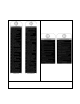
Table 5-5 Suspender Wear Measurements Hoist Type CF or CB Trolley Capacity 1/2 1 2 3 5 Hoist Applied Capacity 1/2 1/2, 1 1 1/2, 2 2 1/2 3 5 d in. (mm) D1 — D2 Limit 0.04 (1) h in. (mm) Standard Limit 0.48 (12.2) 0.512 (13.0) 0.64 (16.2) 0.669 (17.0) 0.06 (1.5) 0.646 (16.4) Standard 0.551 (14.0) 0.709 (18.0) 0.866 (22.0) 1.063 (27.0) 0.945 (24.0) 1.299 (33.0) h Trolley Capacity 1/2 1 2 3 5 D2 – D1 Limit 0.04 (1) 0.06 (1.5) Standard in. (mm) 0.40 (10) 0.51 (13) 0.75 (19) 0.
Table 5-5 (Continued) Suspender Wear Measurements TCR SUSPENDERS d Trolley Capacity D2 – D1 Limit Standard in. (mm) Limit in. (mm) 0.04 (1) 0.51 (13) 0.55 (13.9) 0.06 (1.5) 0.80 (20) 0.82 (20.8) 0.55 (14) 0.57 (14.6) 1.38 (35) 1.43 (36.4) 1/4 1/2 – 1 2 3 6 .
6.0 Maintenance & Handling 6.1 Lubrication 6.2 6.1.1 Lubricate the following trolley components with NLGI (National Lubricating Grease Institute) #2 or equivalent grease. 6.1.2 Track Wheel Gear – Clean and re-grease the Track Wheel gears and Hand Wheel output pinion every three months (more frequently for heavier usage or severe conditions). Do not use an excessive amount of grease and avoid getting any grease on the running surfaces of the Track Wheels or the beam. 6.1.
7.0 Warranty All products sold by Harrington Hoists, Inc.
This Page Intentionally Left Blank 60
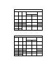
8.0 1/2 to 20 Ton Parts List When ordering Parts, please provide the Hoist code number, lot number and serial number located on the Hoist nameplate (see fig. below). Reminder: Per sections 1.1 and 3.5.1 to aid in ordering Parts and Product Support, record the Hoist code number, lot number and serial number in the space provided on the cover of this manual. TF2/TS2 Series Nameplate The parts list is arranged into the following sections: Section ½ to 5 Ton Page 8.1 TF2 Push Trolley Parts – 1/8 to 5 Ton .
8.
8.1 TF2 Push Trolley Parts – 1/8 to 5 Ton Figure No.
8.
8.2 TF2 Geared Trolley Parts – 1/8 to 5 Ton Figure No.
8.
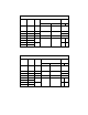
8.3 TS2 Push Trolley Parts – 1/8 to 5 Ton Figure No.
8.
8.4 TS2 Geared Trolley Parts – 1/8 to 5 Ton Figure No.
8.
8.
8.6 TF/TS Push/Geared Trolley Parts for ER2 Hoist – 8 to 10 Ton Trolley Fixing Shaft is shown in front of Suspension Shaft for clarity.
8.6 TF/TS Push/Geared Trolley Parts for ER2 Hoist – 8 to 10 Ton Figure No.
8.
8.7 TF/TS Geared Trolley Parts for CB Hoist – 15 to 20 Ton Figure No.
8.7 TF/TS Geared Trolley Parts for CB Hoist – 15 to 20 Ton Figure No.
This Page Intentionally Left Blank 77
8.
8.8 TF/TS Geared Trolley Parts for ER2 Hoist – 15 to 20 Ton Figure No.
www.harringtonhoists.com Harrington Hoists, Inc. 401 West End Avenue Manheim, PA 17545-1703 Phone: 717-665-2000 Toll Free: 800-233-3010 Fax: 717-665-2861 Harrington Hoists – Western Division 2341 Pomona Rd.